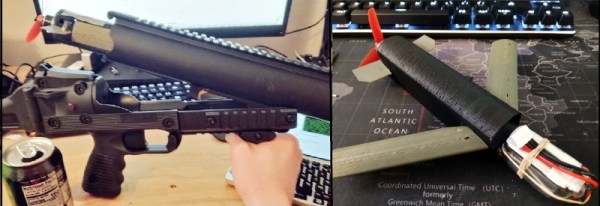
You might think that tiny autonomous drones that can be fired out of a standard 40 mm grenade launcher for rapid deployment would be the kind of thing the military would love to get their hands on. Which is true, of course, and a number of companies are working on the idea for police and military applications. But [Glytch] thinks the technology could also be used for search and rescue operations, so he’s working on creating a version for us civilians.
During his presentation “3D Printing Canister-Launchable Drones for City-Scale Wardriving” at the 2019 CircleCityCon, [Glytch] gave an overview of his progress towards creating a small fixed-wing Unmanned Aerial Vehicle (UAV) that can be built even by those of us who don’t have the budgets of a three letter government agency. He’s not at the point where he can do a test launch just yet, but the design is coming along nicely, and we’re extremely interested in seeing where it goes from here.
 The only way you’re fitting a winged aircraft into the bore of a 40 mm launcher is by folding it up, and so far, that’s where [Glytch] has directed most of his efforts. The wings of his UAV will use a rigid leading edge that folds flat until deployment. When in flight mode, ripstop nylon attached between the body of the drone and the leading edge will be pulled taught to form the actual wing surface; think of it sort of like a bat’s wing. A similar trick will be used for the two control surfaces at the rear of the craft.
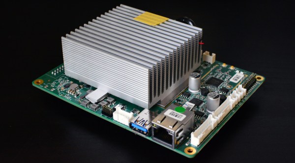
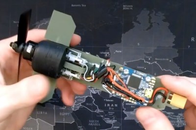
Internally, the UAV is using all off-the-shelf components which [Glytch] hopes will keep it cheap enough that they could eventually be mass produced. As he explained in a recent YouTube video, the motor, speed controller, receiver, and flight controller, are all the sort of thing you’d expect to find in a small RC quadcopter. To make it easier to manage the UAV in the field, the batteries and payload will be housed in a detachable nose cone; allowing the user to rapidly configure the hardware for different missions.
Right now, [Glytch] says the biggest obstacle keeping his drone out of the air is finding a foldable propeller with the specific characteristics he requires. Unable to find anything commercially available, he’s currently looking into designing it himself and having it 3D printed on an SLA machine. He also needs to design a sabot to hold the drone as it travels through the barrel of the launcher. Incidentally, he’s currently testing his design with an Airsoft grenade launcher, as he doesn’t want to wade through the paperwork involved in getting the real deal.
[Glytch] is no stranger to the world of high-tech UAVs. The “Watch Dog” inspired hacking drone he created last year was a huge hit, and he’s recently been working on a HD video and telemetry link over WiFi with the Raspberry Pi Zero for his flying creations.
Continue reading “Designing A Drone To Fire From A Grenade Launcher” →
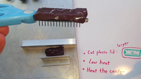
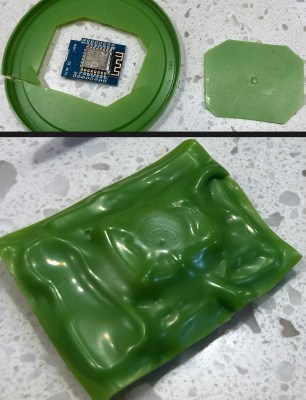 your magic smoke. Even if you are lucky, stray parts are the root of boundless malfunctions from disruptive to deadly. [TheRainHarvester] shares his trick for covering an Arduino Nano with some scrap plastic most of us have sitting in the recycling bin. The video is also after the break. He calls this potting, but we would argue it is a custom-made cover.