Technology vanishes. It either succeeds and becomes ubiquitous or fails. For example, there was a time when networking and multimedia were computer buzzwords. Now they are just how computers work. On the other hand, when was the last time you thought about using a CueCat barcode reader to scan an advertisement? Then there are the things that have their time and vanish, like pagers. It is hard to decide which category digital cameras fall into. They are being absorbed into our phones and disappearing as a separate category for most consumers. But have you ever wondered about the first digital camera? The story isn’t what you would probably guess.
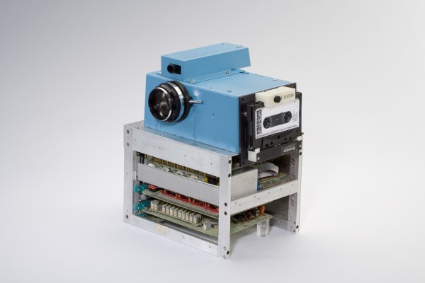
The first digital camera I ever had was a Sony that took a floppy disk. Surely that was the first, right? Turns out, no. There were some very early attempts that didn’t really have the technology to make them work. The Jet Propulsion Laboratory was using analog electronic imaging as early as 1961 (they had been developing film on the moon but certainly need a better way). A TI engineer even patented the basic outline of an electronic camera in 1972, but it wasn’t strictly digital. None of these bore any practical fruit, especially relative to digital technology. It would take Eastman Kodak to create a portable digital camera, even though they were not the first to commercialize the technology.