The Joo Janta 200 super-chromatic peril-sensitive sunglasses were developed to help people develop a relaxed attitude to danger. By following the principle of, ‘what you don’t know can’t hurt you,’ these glasses turn completely opaque at the first sign of danger. In turn, this prevents you from seeing anything that might alarm you.
Here we see the beginnings of the Joo Janta hardware empire. For his Hackaday Prize entry, [matt] has created Nope Glasses. Is that meeting running long? Is your parole officer in your face again? Just Nope right out of that with a wave of the hand.
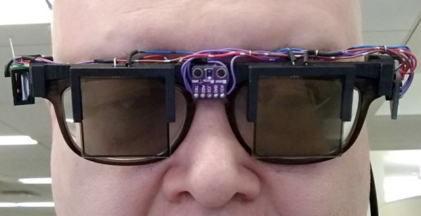
The Nope Glasses are two LCD shutters mounted in a pair of 3D printed glasses. On the bridge of the glasses is an APDS 9960 gesture sensor that tracks a hand waving in front of the glasses. Waving your hand down in front of the glasses darkens the shutters, and waving up makes them clear again. Waving left flashes between clear and dark, and waving right alternates each shutter.
In all seriousness, there is one very interesting thing about this project: how [matt] is attaching these LCD shutters to his glasses. This was done simply by taking a picture of the front and top of his glasses, converting those to 1-bit BMPs, and importing that into OpenSCAD. This gave him a pretty good idea of the shape of his glasses, allowing him to create an ‘attachment’ for his glasses. It’s great work, and we’d really like to see more of this technique.