So you want to photograph Eclipse 2017 but you don’t want to rush out and buy an expensive DSLR just for the event? Not a problem, if you build this simple smartphone filter and occluder.
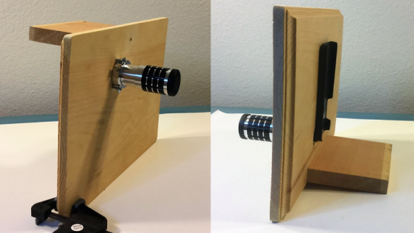
It all started innocently enough for [Paul Bryson] with his iPhone and a lens from those cheap cardboard eclipse glasses we’re starting to see everywhere. Thinking that just taping the filter over the stock lens would do, [Paul] got a painful faceful of sunshine when he tried framing a shot. Turns out the phone body was not big enough to blot out the sun, and besides, the stock lens doesn’t exactly make for a great shot. So with an iPhone telephoto lens affixed to a scrap of wood and a properly positioned filter, [Paul] has a simple rig that’ll let him get some great pre-totality shots of the eclipse, and it’ll be easy to bust out the phone for two minutes of totality selfies. Looks like this setup would be easy to adapt to other phones, too.
We’re all over Eclipse 2017, from Hackaday Eclipse Meetups in at least four different points along the path of totality to experiments on relativity to citizen science efforts so you can get in on the action too. Mark your calendars – August 21 will be here before you know it.