If you are a radio enthusiast it is very likely that you will own at least one software defined radio. With the entry point into the world of SDRs starting with the ultra-cheap RTL2382 based USB receiver sticks originally designed for digital TV, it’s a technology that passed long ago into the impulse purchase bracket.
If you are not a radio enthusiast, or not even a Hackaday reader, you may not have heard of SDR technology. Even the humblest up-to-date radio or TV may well contain it somewhere within its silicon, but at the user interface it will still resemble the device you would have had in the 1950s: analogue tuning, or a channel-flipper.
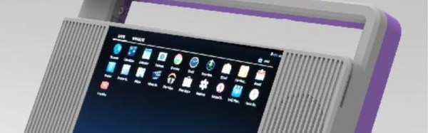
It is interesting to see an attempt to market a consumer device that is unashamedly an SDR, indeed that is its unique selling point. The Titus II SDR bills itself as the “World’s First Consumer Ready SDR Package”, and is based around an Android tablet mated with a 100 kHz to 2 GHz SDR tuner and a pair of speakers in a portable radio styled case. It will support all modes including digital broadcasting through software plugins, and there will be an open plugin API for developers. They are taking pre-orders, and claim that the launch price will be under $100.
It sounds like an exciting product, after all who wouldn’t want a radio with those capabilities at that price! However it leaves us wondering whether the price point is just a little too ambitious for the hardware in question, and we’ll reluctantly say we’ll believe it when we see real devices on the market. A $100 consumer price doesn’t get you much in the tablet world, and that is from high-volume Chinese manufacturing without the extra cost of the SDR hardware and the overhead of smaller volume from a niche product. There are pictures online of real prototypes at trade shows, but we’d like to see a website with fewer renders and more hard plastic.
There is another angle to this device that might interest Hackaday readers though. It should remind anyone that building one yourself is hardly a difficult task. Take an RTL2382 stick with or without the HF modification, plug it into a tablet with an OTG cable, install an app like SDR Touch, and away you go. 3D print your own case and speaker surrounds as you see fit, and post the result on hackaday.io.
Via the SWLing Post.