The Citadel Is The King Of K’nex Builds.

Following one’s passion can lead to amazing results. Sometimes this results in technological marvels; other times, one marvels at the use of the technology. An exemplary display of the latter is The Citadel.

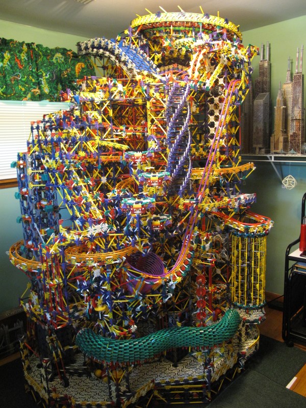
Over the course of three years, redditor [Shadowman39] pieced together this monstrous K’nex structure. With over 17 different paths(!), 45 different elements, and over 40,000 parts, you would expect some meticulous planning to go into its construction — but that’s not the case! [Shadowman39] assembled it largely on the fly with only a few elements needing to be sketched out and only the main elevator proving to be troublesome. Three motors power the structure — one for the main elevator, one for the smaller lifts on the bottom, and one for the release gates.

This is an absolute leviathan hobby project. To satiate the obvious curiosity of anyone who stumbles across this picture, its intricacies can be seen in the video:

Continue reading “The Citadel Is The King Of K’nex Builds.”

Automating A Microscope For CNC Micrographs

[Maurice] is a photographer specializing in micrographs. These very large images of very small things are beautiful, but late last year he’s been limited by his equipment. He needed a new microscope, one designed for photography, that had a scanning stage, and ideally one that was cheap. He ended up choosing a microscope from the 80s. Did it meet all his qualifications? No, but it was good enough, and like all good tools, capable of being modified to make a better tool.

This was a Nikon microscope, and [Maurice] shoots a Canon. This, of course, meant the camera mount was incompatible with a Canon 5D MK III, but with a little bit of milling and drilling, this problem could be overcome.

That left [Maurice] with a rather large project on his hands. He had a microscope that met all his qualifications save for one: he wanted a scanning stage, or a bunch of motors and a camera controller that could scan over a specimen and shoot gigapixel images. This was easily accomplished with a few 3D printed parts, stepper motors, and a Makeblock Orion, an Arduino-based board designed for robotics that also has two stepper motor drivers.

With a microscope that could automatically scan over a specimen and snap a picture, the only thing left to build was a piece of software that automated the entire process. This software was built with Processing. While this sketch is very minimal, it does allow [Maurice] to set the step size and how many pictures to take in the X and Y axis. The result is easy automated micrographs. You can see a video of the process below.

Continue reading “Automating A Microscope For CNC Micrographs”

Hackaday Prize Entry: A Universal Glucose Meter

If you need an example of Gillette’s razor blade business plan, don’t look at razors; a five pack of the latest multi-blade, aloe-coated wonder shaver is still only about $20. Look a glucose meters. Glucose meters all do the same thing – test blood glucose levels – but are imminently proprietary, FDA regulated, and subsidized by health insurance. It’s a perfect storm of vendor lock-in that would make King Gillette blush.

For his Hackaday Prize entry, [Tom] is building what was, until now, only a dream. It’s a universal glucometer that uses any test strip. The idea, of course, is to buy the cheapest test strip while giving the one-fingered salute to the companies who release more models of glucometers in a year than Apple does phones.

As with any piece of consumer electronics, there are plenty of application guides published by the biggest semiconductor companies explaining to engineers how to use their part to build a device. After reviewing the literature from TI, Maxim, Freescale, and Microchip, and a few research articles on the same subject, [Tom] has a pretty good idea how to build a glucometer.

The trick now is figuring out how to build an adapter for every make and model of test strip. This is more difficult than it sounds, because some test strips have two contacts, some have three, some have five, and all of them are proprietary. Calibration will be an issue, but if you’re building a glucometer from scratch, that’s not a very big problem.

This is one of the most impressive projects we’ve seen in this year’s Hackaday Prize. No, it shouldn’t be the only way a diabetic tracks their sugar levels, but diabetics shouldn’t rely only on test strips anyway. If you’re looking for a Hackaday Prize project that has the potential to upend an industry, this is the one.

The HackadayPrize2016 is Sponsored by:

Analog Guts Display GPS Velocity In This Hybrid Speedometer

A digital dash is cool and all, but analog gauges have lasting appeal. There’s something about the simplicity of a purely mechanical gauge connected directly to a vehicle’s transmission. Of course that’s not what’s hapenning here. Instead, this build is an analog display for GPS-acquired speed data.

The video below does a good job at explaining the basics of [Grant Stephens]’ build. The display itself is a gutted marine speedometer fitted with the movement from a motorcycle tachometer. The tach was designed to take a 4-volt peak-to-peak square wave input signal, the frequency of which is proportional to engine speed. To display road speed, [Grant] stuffed an ATTiny85 with a GPS module into the gauge and cooked up a script to convert the GPS velocity data into a square wave. There’s obviously some latency, and the gauge doesn’t appear to register low speeds very well, but all in all it seems to match up well to the stock speedo once you convert to metric.

There’s plenty of room for improvement, but we can see other applications where an analog representation of GPS data could be useful. And analog gauges are just plain fun to digitize – like these old meters and gauges used to display web-scraped weather data.

Continue reading “Analog Guts Display GPS Velocity In This Hybrid Speedometer”

One Man’s Journey To Build Portable Concrete 3D Printer Produces Its First Tiny House

[Alex Le Roux] want to 3D print houses.  Rather than all the trouble we go through now, the contractor would make a foundation, set-up the 3D printer, feed it concrete, and go to lunch.

It’s by no means the first concrete printer we’ve covered, but the progress he’s made is really interesting. It also doesn’t hurt that he’s claimed to make the first livable structure in the United States. We’re not qualified to verify that statement, maybe a reader can help out, but that’s pretty cool!

The printer is a very scaled gantry system. To avoid having an extremely heavy frame, the eventual design assumes that the concrete will be pumped up to the extruder; for now he is just shoveling it into a funnel as the printer needs it. The extruder appears to be auger based, pushing concrete out of a nozzle. The gantry contains the X and Z. It rides on rails pinned to the ground which function as the Y. This is a good solution that will jive well with most of the skills that construction workers already have.

Having a look inside the controls box we can see that it’s a RAMPS board with the step and direction outputs fed into larger stepper drivers, the laptop is even running pronterface. It seems like he is generating his STLs with Sketch-Up.

[Alex] is working on version three of his printer. He’s also looking for people who would like a small house printed. We assume it’s pretty hard to test the printer after you’ve filled your yard with tiny houses. If you’d like one get in touch with him via the email on his page. His next goal is to print a fully up to code house in Michigan. We’ll certainly be following [Alex]’s tumblr to see what kind of progress he makes next!

Inside The Supplyframe Design Lab On Opening Night

Last week the Supplyframe Design Lab in Pasadena opened it’s doors, welcoming in the community to explore the newly rebuilt interior which is now filled with high-end prototyping and fabrication tools and bristling with work areas to suit any need. I had a chance to pull a few people aside during the opening night party to talk about how the Design Lab came about and what we can expect coming out of the space in the near future.

Opening night was heavily attended. I recognized many faces, but the majority of those exploring the building were new acquaintances for me. This is likely due to a strong connection the Design Lab is building with the students, faculty, and graduates of the ArtCenter College of Design. Located just down the road, it is one of the top design schools in the world.

Continue reading “Inside The Supplyframe Design Lab On Opening Night”

Reverse Engineering Quadcopter Protocols

Necessity is the mother of invention, but cheap crap from China is the mother of reverse engineering. [Michael] found a very, very cheap toy quadcopter in his local shop, and issued a challenge to himself. He would reverse engineer this quadcopter’s radio protocol. His four-post series of exploits covers finding the right frequency for the radio, figuring out the protocol, and building his own remote for this cheap toy.

[Michael] was already familiar with the capabilities of these cheap toys after reading a Hackaday post, and the 75-page, four language manual cleared a few things up for him. The ‘Quadro-Copter’ operated on 2.4GHz, but did not give any further information. [Michael] didn’t know what channel the toy was receiving on, what data rate, or what the header for the transmission was. SDR would be a good tool for figuring this out, but thanks to Travis Goodspeed, there’s a really neat trick that will put a 2.4GHz nRF24L01+ radio into promiscuous mode, allowing [Michael] to read the transmissions between the transmitter and quadcopter. This code is available on [Michael]’s github.

A needle in an electromagnetic haystack was found and [Michael] could listen in on the quadcopter commands. The next step was interpreting the ones and zeros, and with the help of a small breakout board and soldering directly to the SPI bus on the transmitter, [Michael] was able to do just that. By going through the nRF24 documentation, he was able to suss out the pairing protocol and read the stream of bytes that commanded the quadcopter.

What [Michael] was left with is a series of eight bytes sent in a continuous stream from the transmitter to the toy. These bytes contained the throttle, yaw, pitch, roll, and a ‘flip’ settings, along with three bytes of ‘counters’ that didn’t seem to do anything.  With that info in hand, [Michael] took an Arduino Nano, an nRF04L01+ transceiver, and a Wii nunchuck to build his own transmitter. If you’re looking for a ‘how to reverse engineer’ guide, it generally doesn’t get better than this.

You can check out a video of [Michael] flying his Wiimoted quadcopter below.

Continue reading “Reverse Engineering Quadcopter Protocols”