A grid of images shows pictures emerging from patches of random noise. To the left, images are more random, while to the right they become more recognizable.

Running Generative AI On An RP2350

Driven by a desire for privacy, customization, and lower costs, there’s growing interest in AI models which can be run on local hardware. Few of them go as far as [Tim], though, who built an image generation diffusion model which can run on an RP2350 microcontroller.

As might be expected, its capabilities are limited. The resolution is 128×128, it only generates images of human faces, and it takes about twenty seconds per image – still impressive for such limited hardware. It runs on a Waveshare RP2350 development board, and it can output the generated image over USB or display it with the aid of a VGA adapter board.

The generative model doesn’t directly create an image. Rather, it generates a distribution in a latent space, which a variational auto-encoder’s decoder component translates into an image. The auto-encoder was trained in two parts: an encoder which transforms an image into a latent-space distribution, and a decoder to transform that distribution back to an image; once this was trained, only the decoder was used.

The generative portion of the model uses a latent flow diffusion transformer; this takes in noise to start with, then iteratively predicts changes which bring it toward the desired image. It can also take in a output class, which guides the generator’s direction (toward a smiling face, for example). [Tim] trained two models, one larger and one faster, and quantized the weights for both to 8-bit integers. Both models, along with the inference program, then fit into 4 MB of flash memory.

For such a small model, the results are remarkably good; they don’t look quite natural, but they’re quite recognizable. For more on how diffusion image generators work, check out our article on Stable Diffusion.
Free Your Rotary Telephone From Its Wire

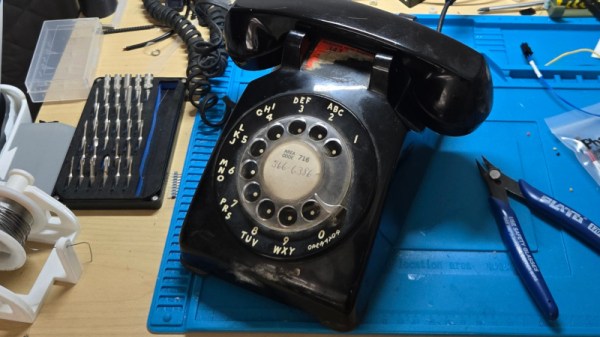
It’s said that a teenager given a rotary telephone in 2026 would be mystified by its operation, yet there are enough surviving instruments for them to be an attractive target for a project. But just what project? [fregacmols] is here with one possibility, turn that old phone into a cellphone.

Connecting to the phone is a subscriber-line interface module, containing all the electronics to simulate a copper phone line. This in turn feeds audio and control wiring to a Lilygo ESP32-S3 board which provides the brains as well as talking to a cellular modem. We especially like that this allows the phone to be used entirely unmodified.

The software does a good job of simulating a North American subscriber line, complete with dial tones, and ringing the phone’s bell on an incoming call. There are a couple of special codes, one to open a wireless network for maintenance, and the other for diagnostic purposes.

Over the years we’ve seen many rotary phone projects, but one which sticks in our mind used an alternative way to connect one to the cellular network.

COSMAC Elf Turns 50

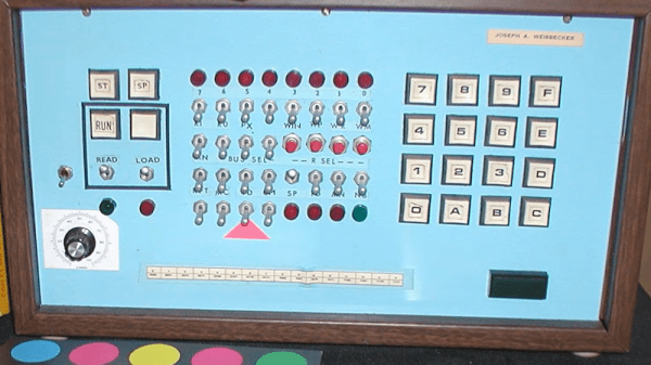
If you were interested in computers in the early 1970s, you struggled to get time on real computers since owning your own was all but impossible. In the middle of the decade, though, you could get a few computers: the Mark VIII, the Altair, the Apple I, and several others. Those were still pretty expensive, though. But in late 1976, an article in Popular Electronics said you could build a “powerful, expandable” computer for $80. The article in question was by [Joseph Weisbecker], who, unknown to most of us at the time, was actually the RCA employee behind the CPU — an RCA 1802. [Tech Time Traveler] takes a close look at the spunky little computer’s history in the video you can see below.

The 1802 was actually the second generation of the CPU, but the first that was all-in-one chip. [Weisbecker] started building the CPU as a personal project. He’d been a hacker even in high school, building relay-based tic-tac-toe games, among other things.

The first incarnation in his lab was “Fred,” with 100 TTL chips, and his idea was to have the computer be at least partially used as a video game — an interesting point, with Pong being very popular at the time.

Continue reading “COSMAC Elf Turns 50”

Parchment Paper Paired With 3D-Printed Grid Gives A Nice Glow

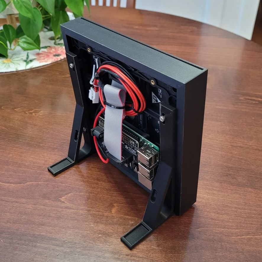
This custom enclosure for a 64×64 RGB LED matrix by [Davisan1001] not only provides a mount point for a Raspberry Pi, but presents a clean and smooth face with square pixels thanks to a 3D-printed grid, some parchment paper, and a sheet of clear plastic.

The first clever thing in this design is the way [Davisan1001] created the grid that acts as a light blocker for each LED in the matrix, preventing light from “spilling” over into its neighbors. Instead of designing the grid from scratch, the solution was just to leverage slicer settings. By printing a flat square with a grid pattern infill and zero solid top and bottom layers, the slicer creates the grid all by itself. A little trial and error was required to get the spacing just right, but it seems to have worked out fine. We’re not sure it’s better than designing a grid in CAD, but it was certainly a clever way to avoid having to do so.

[Davisan1001] also struggled to find an effective and economical solution for a diffuser. Certainly, high-quality diffuser films are available for sale, as are specialty acrylic sheets, but surely there was some household DIY option to do the trick. A sheet of plain white paper blocks too much light. Wax paper handles poorly, and off-angle viewing is poor. The sweet spot was parchment paper.

Parchment paper is commonly used in baking and is thin, easy to handle, flat and even in color, and just opaque enough to act as an effective diffuser while still transmitting enough light to not impede clarity. Cover the LED matrix with the 3D-printed grid, lay parchment paper over that, cover with a sheet of clear plastic, and the job is done.

Light diffusion can be tricky to get just right in a DIY project, and what works for one application won’t necessarily work for another. Our community had loads of suggestions on different solutions, so consider this one more idea to try the next time you have a project that calls for it.

Fixing An Expensive Seagate LaCie Hard Drive Array

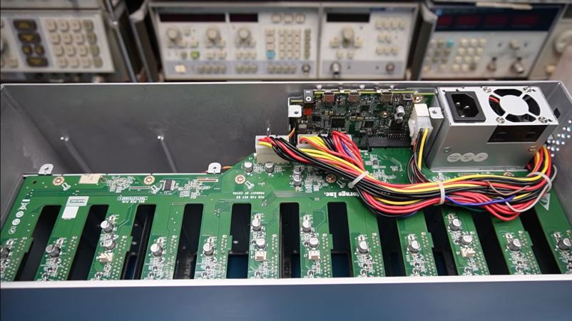
After the [Slow Mo Guys] acquired a 168 TB Seagate LaCie Thunderbolt 3-based RAID storage system back in 2019 to store their video footage, they were obviously slightly miffed when suddenly it would just refuse to power up. Naturally the device was now out of warranty, the product itself no longer produced and Seagate support was less than supportive, ergo they sent the device to [Mend it Mark] for an attempted repair.

At first inspection the device appeared to be basically unresponsive, with none of the four fans running and no signs of life other than a few lit LEDs on the main PCB after supplying power to it. After full disassembly and with no repair guide or schematics to go by [Mark] had to start from basics, first diagnosing whether all the power rails were turning on, which they weren’t.

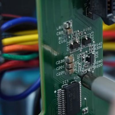
Eventually this led to the NXP LPC11U6x-series MCU which acts as the main power management and monitoring chip in the system. [Mark] deduced that this MCU wasn’t turning on all the power rails because it was waiting for a signal from the fan controllers on the SATA backplane. With the MCU sending the right signals here, and the fans all working when directly supplied with power, ultimately it turned out that a single SI2319 or similar P-channel MOSFET in SOT-23 package near one of the fan connectors had gone faulty.

Replacing this one MOSFET seems to have fixed the RAID array, with it now happily powering up, although the real test will be once the [Slow Mo Guys] start shoving the HDDs back into it. Assuming that this was the sole fault in the system, then it was a very cheap fix in terms of materials. It’s a real shame that repair guides or schematics aren’t made available for devices like this, even if just after they stop being produced.

Continue reading “Fixing An Expensive Seagate LaCie Hard Drive Array”

Making A Pole Balance Itself With Propellers

A fun trick with a pole is to try to balance it so that it can stand on one end. This can be done in a few ways, such as by exerting a force on either end to counterbalance any force that threatens to make it fall over. The approach that [Peter Ryseck] chose was to cobble together what is effectively a flying drone for on top of a standing pole, without cheating such as by simply lifting it off the ground.
Getting to the point where the drone could react quickly enough to changes in the pole’s orientation was the hardest part, as the quieter, larger propellers also have a lot more inertia. This ruled out using 10″ blades, while triple 5″ blades seemed to work well enough. For the avionics a standard quadcopter control board and software is used, with the programming such that it’ll react appropriately without causing additional instabilities.

Naturally making this work took some trial and error, with issues like oscillations plaguing the system. One unexpected problem was that the pole – taken from a pool fishing net – was flexible enough to add its own instabilities to the system. In the video all these issues and their solutions are explained in detail, along with the ultimate result. One very neat solution here for example is to have the pole lean into the wind, which is a more stable configuration than insisting on having the pole be at a perfect ninety degrees with the ground.

Continue reading “Making A Pole Balance Itself With Propellers”

Repairing Traces On A Delidded Pentium III CPU Gone Wrong

Delidding a CPU involves removing the integrated heat spreader (IHS) that’s put over the bare die and the substrate that it is mounted on. The reason for this is usually to improve cooling performance, as the IHS is effectively a small heatsink between the die and the large heatsink, adding more problematic thermal interfaces. If delidding is done improperly it can cause severe damage to the substrate, as in the case of a very nice 1.3 GHz Tualatin Pentium III CPU that [Bits und Bolts] got in an eBay lot with nasty delidding damage.

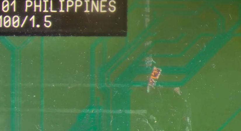
With the delidding enthusiast presumably having used brute force and ignorance combined with a prying implement, around a dozen of tiny traces on the substrate got severed, requiring tedious trace repair to fix. After confirming that with the severed traces the CPU is indeed busted, enough of the soldermask is removed to make a repair.

Any traces that were still good got covered with soldermask, while for the remainders the thinnest available copper wire was used to create new traces. Although very much doable with a good microscope and a steady hand, this is definitely one of those things that’s much easier to prevent than to fix.

With IHSes having become standard on CPUs, delidding continues to this day, with increasing risks of severed traces and ripped-off capacitors should it go wrong. Although those newer CPU substrates are probably not repairable, repairing these older CPUs instead of tossing them as e-waste seems plausible at least.

Continue reading “Repairing Traces On A Delidded Pentium III CPU Gone Wrong”