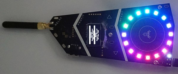
[Bunnie] was at Burning Man this year, and to illuminate his camp members in the dark and dusty nights of the playa, he created a blinky badge. This isn’t just any badge stuffed with RGB LEDs; each of the badges were unique by the end of Burning Man. These badges were made unique not by twiddling dials or pressing buttons; all the color patterns were bred with badge sex.
This social experiment to replicate nature’s most popular means of creating more nature is built around a peer to peer radio. Each badge is equipped with a radio, a circle of RGB LEDs, and a bit of code that expresses the pattern of lights on the badge as a sequence of genes. When one badge gives consent to another badge, they ‘breed’, creating a new pattern of lights. If you’re wondering about the specifics of the act, each badge is a hermaphrodite, and each badge transmits a ‘sperm’ to fertilize the other plant’s ‘egg’. There’s even a rare trait included in the genome of the badge; each badge has a 3% chance of having a white pixel that moves around the circle of LEDs. [Bunnie] found this trait was more common after a few days, suggesting that people were selectively breeding their badges.
Of course, finding potential mates is a paramount concern for any sexual organism, and the sex badge has this covered, too. The 900MHz radio listens for other badges in close proximity, and when any are found their owners are displayed on an OLED display. This came in handy for [Bunnie] more than a few times – there’s no phones out there, and simply knowing your friends are within a hundred meters or so is a big help.
The entire badge platform is documented online, along with the code and spec for badge genes. Badges with some sort of wireless communication have been around for a while, but this is the first time that communication has been used for something more than sharing contact information or implementing a chat room. It’s a great idea, and something we hope to see more of in future con badges.
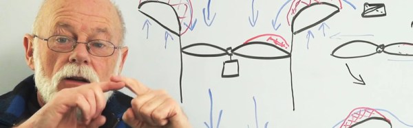
Want to learn why ducted propellers improve both thrust and efficiency? Well, we’ve got both the lesson and the teacher for you. [Bruce Simpson] isn’t exactly a household name, but we bet most of you already know who he is. He’s the guy from New Zealand that in 2003 set out to make a $5000 DIY Cruise Missile – and he claims that he would have succeeded if the NZ Government hadn’t got in the way. Now-a-days [Bruce] focuses most of his energy on his two YouTube channels, RC Model Reviews and XJet.
Back to the lesson at hand: In the video after the break, he does a wonderful job explaining how the walls of a duct work to stop the high pressure area of the propeller from moving to the low pressure area. You’ll see something similar on the wings of jets aircraft. There will be a small vertical fin on the end of the wing, and much like a duct, it’s job is to physically separate the two areas and prevent tip vortex effects. That in turn increases efficiency. [Bruce] has some other great RC/model type videos, so if you like what you see, you might want to subscribe. Or you can learn more about the DIY Cruise Missile saga.
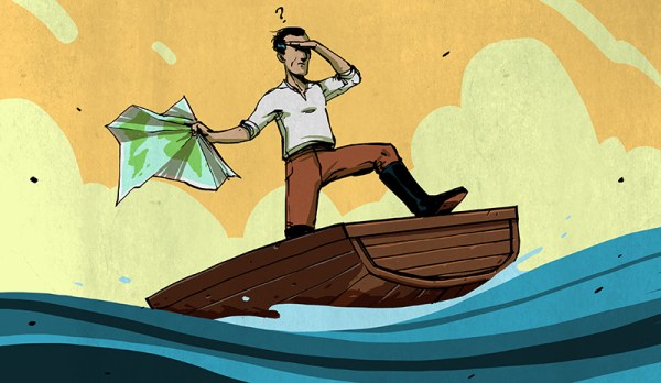
I came across an interesting question this weekend: how do you establish your East/West location on the globe without modern technology? The answer depends on what you mean by “modern”, it turns out you only have to go back about three centuries to find there was no reliable way. The technology that changed that was a clock; a very special one that kept accurate time despite changing atmospheric conditions and motion. The invention of the Harrison H1 revolutionized maritime travel.
We can thank Andy Weir for getting me onto this topic. I just finished his amazing novel The Martian and I can confirm that George Graves’ opinion of the high quality of that novel is spot on. For the most part, Andy lines up challenges that Mark Watney faces and then engineers a solution around them. But when it came to plotting location on the surface of Mars he made just a passing reference to the need to have accurate clocks to determine longitude. I had always assumed that a sextant was all you needed. But unless you have a known landmark to sight from this will only establish your latitude (North/South position).
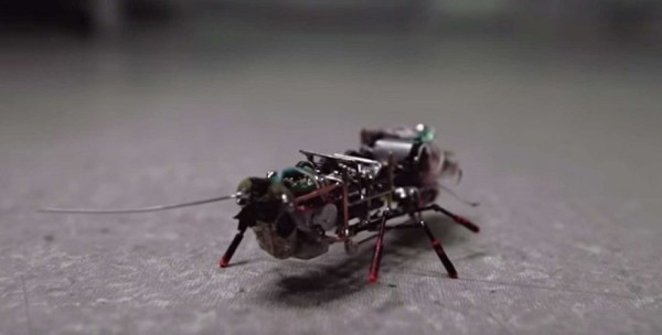
It’s name is Blaberus Cranifer, or Death’s Head for short. Light has now been shed on this once secret project built by the Immanuel Kant Baltic Federal University for a “vague” Russian organization. The little guy has a 20 minute battery life and can carry a 10 gram payload. Which comes in handy when you want to sneak a camera into hard to reach places. Other requirements were for it to look and behave like a real live insect.
It’s an impressive project considering it was built from scratch in only seven months time. Its intricate gears and other mechanical features would require the hands of a skilled watch maker to construct. Alternatively, one can control live insects such as controlling a roach’s brain or hooking up some radio controls to a live beetle. But building robotic insects is still pretty cool.
Be sure to check out the well made video detailing some of the project’s build process.
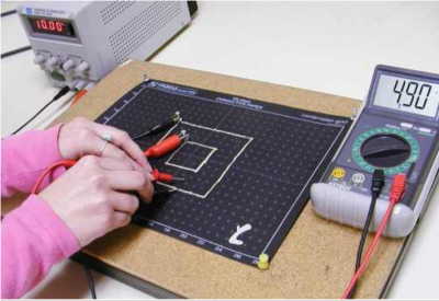
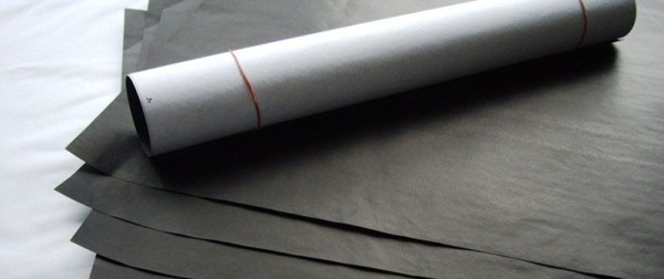
Legendary electrical engineer and linear IC trailblazer Bob Widlar was just like you. What I mean is that he would use everything available to him to mock up circuits, create prototypes, and make things work. One of the simplest and coolest tools he used was a conductive paper called Teledeltos. This wonderful stuff allowed him to define and test various configurations for the oddly-shaped ballast resistors he used in some of his high-performance circuit designs. But it wasn’t created for people like you and Bob. Teledeltos paper was created and trademarked by communications giant Western Union to drastically improve the convenience of telegrams.
Development of the electric telegraph ushered in the era of global communication. Suddenly, people could send messages to the other side of the world in a fraction of the time it took by post. The telegraph absolutely revolutionized human communication. It was the e-mail and the Twitter of its time. The telegraph’s efficiency made the Pony Express pretty much obsolete by the 1860s. And for a very long time it was much cheaper for people to send a telegram than make a long-distance phone call.
The Advantages of Facsimile
Translated from ancient Greek, ‘teledeltos’ basically means writing tablet at a distance. Western Union began developing Teledeltos paper in the 1930s for the purpose of transmitting telegrams by facsimile, a method that would greatly reduce the time it took to input messages into the system and get them out on the other side. As long as both the sender and the receiver had facsimile machines, a handwritten telegram could be transmitted without having to be typed by a clerk or translated into code. Teledeltos paper was also used in a variety of chart recorders, like seismographs and map plotters. The ability to feed a handwritten message, a photograph, or a map of enemy territory into a machine that transmitted an exact copy was a real game changer.
Because of its composition, Teledeltos paper could be easily marked without an electrolyte. It marked so well that photographs and other graphic information could be transmitted, and no processing was required on the receiving end. A dry recording paper is also much less sensitive to light and to temperature extremes. More importantly, properly stored dry paper is impervious to fungal growth. Teledeltos paper could sit around indefinitely without becoming useless. The only real disadvantage to this type of paper was the somewhat laborious process that went into achieving the desired resistance. Fax machines eventually moved on to digital transmission and thermal printing technology.
Teledeltos paper has a light gray electro-sensitive coating on one side, and the other side is carbon black. When a current is applied with a stylus to the coated side of the paper, the coating is instantly burned away, revealing the carbon black. Teledeltos paper could be marked using either AC or DC. Polarity didn’t matter, either, but the boys in the lab at Western Union had better luck when they used a positive stylus with DC rather than a negative one.
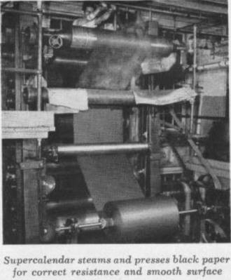
Teledeltos paper was made in two types—“L” for low resistance and “H” for high. The resistivity of a roll of Teledeltos paper depended on the quality of the conductive fibers that went into it. The paper’s electrical characteristics were also influenced by the fiber beating process and the distribution of the conductive fibers by the supercalender, a system of hard rollers used in papermaking and other processes that press and smooth paper and other materials to increase the density.
Teledeltos to the Rescue
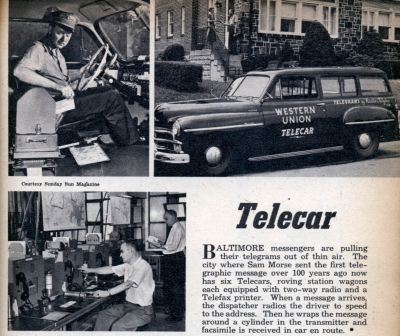
The Western Union Telecar printed telegrams on the go and delivered them to homes and businesses. Image credit: Modern Mechanix
Western Union was eager to extend its reach into private businesses and public places so that patrons who weren’t heavy telegram users didn’t have to visit a telegram office in order to share a bit of good news or to send their condolences. The company’s Telefax division came up with several types of machines to serve different business needs.
Some messages continued to be delivered by hand, but they weren’t printed at the central office. Western Union created a Telecar service to print telegrams transmitted to the car by the central office and deliver them to people’s homes. Messages were printed onto recording blanks that were cut automatically by a Telefax recorder situated in the car’s passenger area. The Telecar’s radio and amplification equipment was in the trunk.
The standard Telefax machine for office use was fairly large, like an early microwave oven. A smaller version called the DeskFax was only about the size of a breadbox, and these units occupied the desks of many businessmen and secretaries because of their convenience.
A Western Union DeskFax unit. Image from [B. Hilpert]Both the Telefax and the DeskFax scanned and recorded telegrams using a rotary drum mechanism. A message could either be typed or handwritten onto a telegram blank. The sender then wrapped the telegram around a drum and set the machine to send. The machine would scan the message optically and then transmit it to the central office.
Before sending it on to the recipient, an attendant at the telegram office had to remove the incoming message and wrap it around the drum of a transmitting machine. Once connected to the receiving party’s line, the far end unit would buzz to arouse attention. The receiving patron would then load a blank on to their DeskFax’s roller and set their machine to receive.
Conductive paper like Teledeltos has many applications aside from fax machines and Fathometers. For starters, it’s great for making one-offs of both standard and variable resistors. Conductive paint can be used as connection points for wires. The paper is also well-suited for simulating current flow through circuits using a fraction of the current intended in production. Vacuum tube designers used Teledeltos for modeling potentials. Teledeltos can also be used to visualize electromagnetic potentials and perform field plotting.
We’re sure that at least a few of our readers out there used Teledeltos or something like it in school or on the job. Did you know you can still buy it? Teledeltos paper itself is still available from two companies in the UK, Better Equipped and Timstar. In the US, you can get it from Pasco in packs of 50 and 100 sheets, with and without a grid pattern.
[Teledeltos paper image is a product photo from Better Equipped]
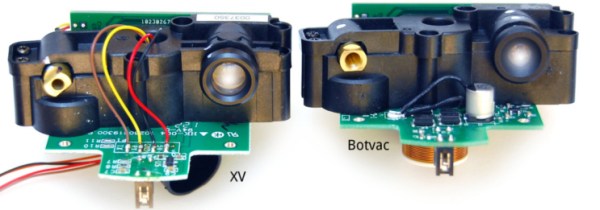
It seems second nature to us and it’s one of the ways we hackers are different from the larger population… sometimes we absolutely insist on buying something that is already broken. Which is where we join [Anton] as he reverse engineers, debugs, and repairs a broken Neato Botvac’s LiDAR system all in the name of having clean floors at a fraction of the cost.
Now keep your head on a swivel ’cause along the way [Anton] has the all-too familiar point in his repair where he puts the original project on hold while he makes a specialized tool he needs to finish the job. It’s hard to tell which is more impressive: turning a laptop webcam into a camera capable of clearly viewing bond wires and (wait for it!) where they are attached on the Silicon, or that he (yeah, we were making a comparison…member?) went straight back to solving the original problem. [Anton] did split this project into two separate blog posts, the first one is linked above and it’s not until the second post that he fixes the original problem. Perhaps there was a bit of scope creep, which was the reason for the separate blog entries? At any rate, [Anton] does a great job documenting the process along with what he calls some ‘juicy pictures’ and you can see a few of them after the break.
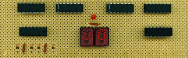
There are two things that keep me from expanding my collecting old computers: the cost and the space required to house them. I do have my old original TRS-80, and an old serial terminal (see the video below). However, I got rid of my Data General hardware and I lost my old 1802 COSMAC Elf in some flooding. There have been a few replica retro computers of various degrees of fidelity and they are usually cheaper and smaller than the originals. I have a replica Altair, a replica Elf, and a replica KIM-1.
However, it is hard to justify the expense and the cost of either the real things or the replicas. It is even worse with the really large machines, some of which require special power or cooling and are hard to keep running. Another option, of course, is software simulation. Options like SIMH and Hercules work well, but they aren’t always graphical and it is a lot of work to set up a machine just to play with for a few hours or to show a student how it was done in the good old days.
![A Western Union DeskFax unit. Image from [B. Hilpert]http://www.cs.ubc.ca/~hilpert/e/deskfax/](https://hackaday.com/wp-content/uploads/2015/09/deskfax.jpg?w=400)