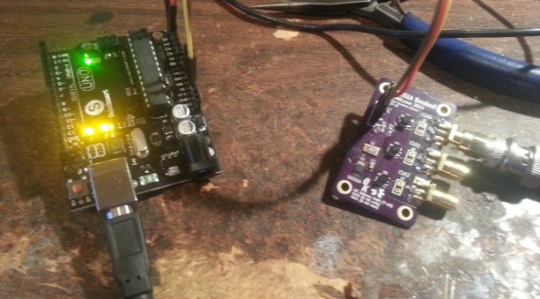
Learning To Reverse Engineer On A Broken Printer

Lexmark Hack

When a Lexmark inkjet printer stopped working, [Mojobobo] was able to claim it as his own. He quickly realized that the machine was flooded with ink and not worth repairing, but that didn’t mean he couldn’t still find a use for it. When he learned that the printer’s firmware was not only upgradable but also unprotected, he knew he should be able to get the printer to do his own bidding.

[Mojobobo] started his journey with the motherboard. The unit still powered up, but it was asking to insert a “duplex module” before it would boot any further. [Mojobobo] first tried to find a way to trick the duplex module sensor, but was unsuccessful. His next step was to search for some kind of serial communications port. He didn’t have an oscilloscope, so instead he used a speaker with a wire probe. In theory, if the wire was pressed against an active serial port, he would be able to hear varying tones through the speaker. Sure enough, he found some interesting tones after probing around some ports next to a “JTAG” label. He looked up some information about the nearby chip and found that it included an SPI bus.

After some internet research, [Mojobobo] learned enough about SPI to have a rough idea of how to use it. Having limited tools available to him, he decided to use his Arduino to try to communicate with the motherboard. After wiring up a simple circuit, (and then re-wiring it) he was able to dump the first 4096 bytes of the motherboard’s boot loader to the Arduino via the SPI interface.

[Mojobobo’s] next steps will be to find a faster way to dump the boot loader. At 9600 baud, he grew tired of waiting after three hours. Once he has the full boot loader he intends to search for a way to bypass the duplex sensor and get the board to finish booting. Then he may just use the printer for its scanning functions, or he might find other interesting uses for it.

Bumpy, The Beautiful DIY MP3 Player

OLYMPUS DIGITAL CAMERA

[Matt]’s been working on a small hombrew MP3 player, and although it’s not much more useful than an iPod Shuffle, sometimes that’s all you need. Besides, it turned out to be a beautiful project, completely custom, and a great example of what a high resolution 3D printer can do with an enclosure design.

Inside Bumpy is an ATMega32u4 with a VS1003 MP3 codec IC. The device is powered by a 1000mAh lithium battery, and the user interface is an exercise in simplicity; a single click/scroll wheel changes the volume, toggles play and pause, and selects the next or previous track. Eight LEDs mounted in the center of the board glow through the case for status, volume, and interface feedback.

By far the most impressive part of Bumpy is the case. It was printed at [Matt]’s place of employment – Formlabs – in white UV curing resin. The pictures show a surface finish that would be difficult to replicated on a squirting plastic style 3D printer, with a textured, bumpy surface that inspired the name.

Eerie Robotic Instruments Make Use Of Servos And Solenoids

Turbo-gusli

Self-playing pianos are so last year. How about a robotic acoustic-gusli?

[Dmitry Morozov] calls it the Turbo-Gusli or Gusli-Samogudy. A Gusli is perhaps the oldest Russian multi-stringed instrument, which resembles a harp and whose exact history is not quite known. Add Samogudy to the name and you’ve got a “self-playing Gusli”.

The eerie sounding music is produced by six individual servo motors, a regular DC motor, a stepper motor, three solenoids, a handful of springs, and 38 strings. It’s all controlled by two Arduino Unos, with the software written in Pure Data, an open source visual programming language.

He’s made several videos of the exhibit, including a performance that sends shivers down our spines — stick around after the break for a listen!

Continue reading “Eerie Robotic Instruments Make Use Of Servos And Solenoids”

Frankensteined X4 Quad Is Brought Back To Life

x4 quadcopter wood frame

As kids we’ve all let a friend use a toy only to have it returned broken. That was such a bummer! At least that was years ago though…. well not for [Tom]. He had a Hubsan X4 mini quadcopter that he had crashed into all sorts of things. The little quad held up good against all of the beatings so [Tom] didn’t think too much about letting his pal take it for a test drive. Thirty seconds later, several separate pieces of the quad were laying in the dirt.

A new X4 was ordered but there was some time to kill waiting for it to show up. Since the electronics seemed to be intact and only the frame was broken [Tom] decided to try his hand at making a new frame. Keeping costs under control is an important part of any project and this one was no different. The frame would be made of cheap and rigid 5mm plywood. The only potential problem would be the weight. [Tom] cut out a piece of the plywood and weighed it, then measured the volume and calculated the density of the wood. The wood’s density was used to estimate the final weight of new plywood frame designs and shapes. This worked so well that the newly built quad only weighed more than the original by 0.31 grams, less than 1% increase in the total weight!

Continue reading “Frankensteined X4 Quad Is Brought Back To Life”

Programming Micros With Impossibly Cheap Bluetooth Adapters

tooth

[Zenios] and [Raivis] are building a small balancing robot, and for communications to the outside world, they’re using a small, extremely cheap Bluetooth adapter. They figured uploading code to the microcontroller over Bluetooth would be a good idea, but their adapter, a cheap HC-06 module, had no way of resetting the microcontroller; it just provided Tx and Rx the serial port. They did notice a LED blinked when a device wasn’t connected to the adapter, so with a simple circuit they kludged a reset circuit where it wasn’t intended.

The small LED on the HC-06 module blinks when nothing is connected, and remains on when a connection is established. Figuring a new connection would be a good time to upload new code, the guys needed to design a circuit that would stay low when the LED was blinking, and switch to high when the LED was on.

A simple RC filter took care of the blinking LED, keeping the line low until a device connected. Bringing the logic level high when the LED stayed solid required digging through a part drawer, eventually finding an LM741 p differential amplifier.

After a few small changes to the bootloader, the guys had a reliable means of flashing new firmware without the need of programming adapters or wires draped over their workspace, all with a Bluetooth adapter that shouldn’t have this capability. Video below.

Continue reading “Programming Micros With Impossibly Cheap Bluetooth Adapters”

Virtual Reality Gets Real With 3 Kinect Cameras

No, that isn’t a scene from a horror movie up there, it’s [Oliver Kreylos’] avatar in a 3D office environment. If he looks a bit strange, it’s because he’s wearing an Oculus Rift, and his image is being stitched together from 3 Microsoft Kinect cameras.

[Oliver] has created a 3D environment which is incredibly realistic, at least to the wearer. He believes the secret is in the low latency of the entire system. When coupled with a good 3D environment, like the office shown above, the mind is tricked into believing it is really in the room. [Oliver] mentions that he finds himself subconsciously moving to avoid bumping into a table leg that he knows isn’t there. In [Oliver’s] words, “It circumnavigates the uncanny valley“.

Instead of pulling skeleton data from the 3 Kinect cameras, [Oliver] is using video and depth data. He’s stitching and processing this data on an i7 Linux box with an Nvidia Geforce GTX 770 video card. Powerful hardware for sure, but not the cutting edge monster rig one might expect. [Oliver] also documented his software stack. He’s using Vrui VR Toolkit, the Kinect 3D Video Capture Project, and the Collaboration Infrastructure.

We can’t wait to see what [Oliver] does when he gets his hands on the Kinect One (and some good Linux drivers for it).

Continue reading “Virtual Reality Gets Real With 3 Kinect Cameras”

A Modular 1GHz Spectrum Analyzer

an

[MrCircuitMatt] has been doing a lot of radio repair recently, quickly realized having a spectrum analyzer would be a useful thing to have. Why buy one when you can build one, he thought, and he quickly began brushing up on his RF and planning out the design of a 1000 MHz spectrum analyzer

The project is based on Scotty’s Spectrum Analyzer, a sweep-mode, modular 1GHz spectrum analyzer that is, unfortunately, designed entirely in ExpressPCB. [Matt] didn’t like this proprietary design software tied to a single board house. The basic building blocks of [Scotty]’s spectrum analyzer were transferred over to KiCAD, the boards sent off to a normal, Chinese board house.

In the second video, [Matt] goes over the design of the control board, a small module that connects the spectrum analyzer to the parallel port of a PC. There’s a lot of well thought out design in this small board, a good thing, too, since he’s powering his VCO with a switched mode supply. The control board has a 32-bit I/O, so how’s he doing that with a parallel port, what is ultimately an 8-bit port? A quartet of 74ACT573, a quad buffer with latch enable. Using the eight data lines on the parallel port allows him to toggle some pins while the ancient pins on the parallel bus – Strobe, Select Printer, and Line Feed control the latches on each of the buffers. This gives him the ability to write to 32 different pins in his spectrum analyzer with a parallel port.

Right now, [Matt] is wrapping up the construction of his control board, with the rest of the modules following shortly. He thinks the completed analyzer might even be cheaper than a professional, commercial offering, and we can’t wait to see another update video.

Continue reading “A Modular 1GHz Spectrum Analyzer”