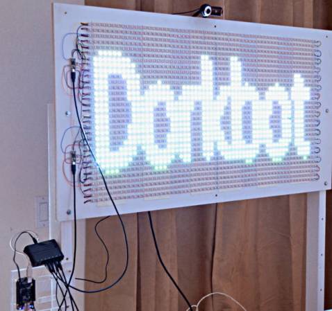
This single digit display is an old edge-lit module that [Ty_Eeberfest] has been working with. The modules were built for General Radio Company and have a really huge PCB to control just one digit. [Ty’s] modules didn’t come with that driver board, so he was left with the task of controlling an incandescent bulb for each digit. After a bit of thought he figured it would be much easier to just replace the edge-light bulbs with a set of LEDs.
We’ve seen these exact modules before, referenced in a project that created an edge-lit Nixie tube from scratch. Each digit in the display is made from a piece of acrylic with tiny drill holes which trace out the numerals. The acrylic is bent so that the edge exits out the back of the module where it picks up light from the bulb. [Ty] laid out his circuit board so that each LED was in the same position as the bulb it was replacing. As you can see, his retrofit works like a charm.
Here’s an Android powered pen plotter that does it all. It was built by [Ytai Ben-Tsvi] to take with him to Maker Faire. He’s the creator of IOIO, a hardware interface module designed to communicate with an Android device via USB (host or OTG are both supported).
The physical hardware is simple enough. He draws on a pad of white paper using a felt-tipped marker. Located at the top of the easel are two wheels with stars etched on them. They are reels which spool and dole-out string to control the pen’s movements. The pen tip can be lifted by a ball bearing mounted just below it.
But the project really takes off when you watch [Ytai’s] demonstration. The Android tablet controlling the device captures a picture of an object — in this case it’s a toy truck. The app then processes it using edge detection to establish how to plot the image.
For those of you who might have forgotten, let’s go over the rules of Centurion. The object of the game is for every minute, for 100 minutes, drink a shot of beer. It doesn’t sound like a lot, but after completing the challenge you’ll have had 3 liters of beer (or about eight and a half 12 oz cans) in just under two hours. When [Peter] played Centurion, he found the biggest problem was – understandably – keeping track of the time and who drank what. For an upcoming weekend of drinking, [Peter] decided to solve this problem once and for all with shift registers and seven-segment displays.
[Peter]’s Centurion score box comes in two parts. The first and largest part of the build is the main board housing an ATMega8 microcontroller and a huge two digit seven-segment display to keep track of the countdown until the next shot. Two other boards house eight additional two digit seven-segment displays for each player, incremented every time a player presses a giant arcade button.
The entire build is designed around a small travel case that also holds a large battery for cordless drinking parties. Let’s just hope the project is reasonably water-resistant; we can see a lot of spills happening in the future. Check out the video demo below.
We’ve been following the work of [Andrew Holme] and his homebrew GPS receiver for a while now. A few years ago, [Andrew] built a four-channel GPS receiver from scratch, but apparently that wasn’t enough for him. He expanded his build last year to track up to eight satellites, and this month added a Raspberry Pi for a 12-channel, battery-powered homebrew GPS receiver that has an accuracy of about 3 feet.
The Raspi is attached to an FPGA board that handles the local oscillator, real-time events, and tracks satellites automatically. The Pi handles the difficult but not time-critical math through an SPI interface. Because the Pi is attached to the FPGA through an SPI interface, it can also load up the FPGA with even more custom code, potentially turning this 12-channel receiver into a 16- or 18-channel one.
An LCD display attached to the FPGA board shows the current latitude, longitude, and other miscellaneous data like the number of satellites received. With a large Li-ion battery, the entire system can be powered for about 5 hours; an impressively portable GPS system that rivals the best commercial options out there.
Do you ever wonder why geese always fly together in a V-shape? We’re not asking about the fact that it makes the work load much less for all but the lead goose. We mean how is it that all geese know to form up like this? It’s is the act of flocking, and it’s long been a subject of fascination when it comes to robotics. [Scott Snowden] researched the topic while working on his degree a few years ago. Above you can see the demonstration of the behavior using LEGO Mindstorm robots. That’s certainly interesting and you’ll want to check out the video after the break. But his offering doesn’t end with the demo. He also posted a huge article about his work that will provide days of fascinating reading.
We can’t begin to scratch the surface of all that he covers, but we can give you a quick primer on his Mindstorm (NXT) setup. He uses these three bots along with a central brick (the computer part of the NXT hardware) which communicates with them. This lets him use a wide range of powerful tools like MatLab and Processing to recognize each robot with a top-down camera, passing it data based on info harvested with computer vision. From there it’s a wild ride of modeling the behavior as a set of algorithms.
[Martin Raynsford] figured out a way to sneak some learning into a fun package. He did such a good job the test subjects didn’t even know they were teaching themselves just a tiny bit of CNC programming.
The apparatus above is a marble maze, but instead of building walls [Martin] simply etched a pattern on the playing field. The marble is a ball bearing which moves through the maze using a magnetic CNC gantry hidden underneath. Where does one get ball bearings of this size? If you’re [Martin] you scavenge them from your laser-cut Donkey Kong game.
He showed off the rig at the Maker Faire. It takes simple commands as cardinal directions and units of movement. The ‘player’ (remember, they’re secretly learning something, not just playing a game) inputs a series of movements such as “N10,E10” which are then pushed through a serial connection to the Arduino. It follows these commands, moving the hidden magnet which drags the ball bearing along with it. It’s simple, but watch the clip after the break and we think you’ll agree the sound of the stepper motors and the movement of the ball will be like crack for young minds.
I’m not above admitting that it is childish of me. I was told I couldn’t have this thing and suddenly I knew I had to make it. I see it with my kids all the time. Toys can sit in a corner collecting dust for ages, but the second it is in threat of being removed, they have renewed interest, at least for a few minutes.
I figured, if I’m going to be childish about it and print a gun that a) won’t work because I don’t have the right printer, and b) I won’t use anyway because I don’t generally play with guns, I might as well make a fun timelapse video of the more recognizable parts being made.
It initially seemed like it was going to be quick and easy. However, I quickly found that just printing this thing was going to be a time consuming and frustrating task.
1. the scale on the individual files was way off.
I suspect this has something to do with the printer it was designed for. It seemed very close to being 1 inch = 1 mm. Not a completely uncommon problem. Manually resizing got some files to look right, but I found many simply wouldn’t resize.
2. Almost every single item had errors.
If you’ve done 3d printing, you’ve found that a model can have all kinds of issues that will stop it from printing correctly. I found every single item for the gun had errors. I actually learned a lot about how to repair non-manifold items from this exercise, so it was good in the end.
Some items, like the hammer and the hammer springs simply would not print. I ran them through systems to repair them and fix errors. It would say that everything was fixed, but when I tried to “slice” them for printing, the software would crash. This means that my gun is incomplete. It has no hammer. Not really that big of a deal to me.
the whole gunNote that it is missing the hammer mechanism. More on that later.disassembled
trigger spring. Cool design, I might use this idea for something else later
black: initial print with errors. Red: fixed print.
the gopro fell into the printer stopping it from moving the bed correctly. You can see the top two layers are shifted about an inch. The rest of that mess is just support material I was ripping out.
The hammer that refused to print correctly despite repeated repairs.
what the hammer was supposed to look like.
the spring that crashed my slicing program every time I tried to prepare it for a print.
Do I care now?
Nope. I climbed to the top of the fridge and got my cookies. I’m a happy child. The reality is that a zip gun is still cheaper, easier, safer, and more reliable. Here’s an example.