Usually when we present a project on these pages, it’s pretty cut and dried — here’s what was done, these are the technologies used, this was the result. But sometimes we run across projects that raise far more questions than they answer, such as with this printed circuit board that’s actually printed rather than made using any of the traditional methods.
Right up front we’ll admit that this video from [Bad Obsession Motorsport] is long, and what’s more, it’s part of a lengthy series of videos that document the restoration of an Austin Mini GT-Four. We haven’t watched the entire video much less any of the others in the series, so jumping into this in the middle bears some risk. We gather that the instrument cluster in the car is in need of a tune-up, prompting our users to build a PCB to hold all the instruments and indicators. Normally that’s pretty standard stuff, but jumping to the 14:00 minute mark on the video, you’ll see that these blokes took the long way around.
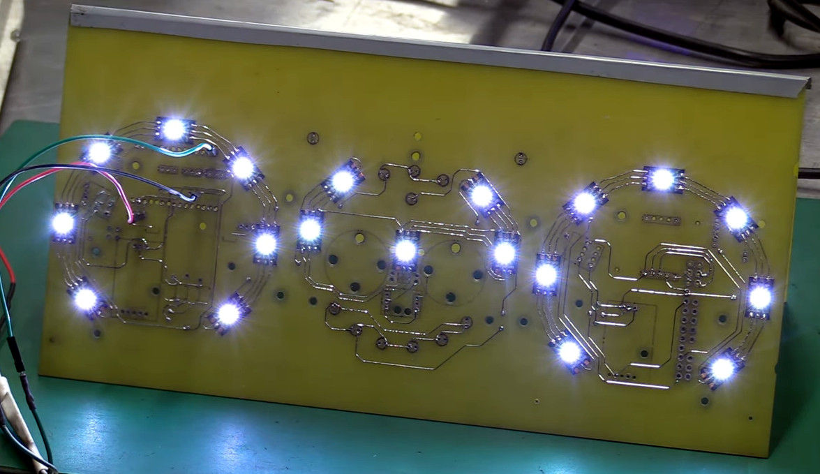
 Starting with a naked sheet of FR4 substrate, they drilled out all the holes needed for their PCB layout. Most of these holes were filled with rivets of various sizes, some to accept through-hole leads, others to act as vias to the other side of the board. Fine traces of solder were then applied to the FR4 using a modified CNC mill with the hot-end and extruder of a 3D printer added to the quill. Components were soldered to the board in more or less the typical fashion.
It looks like a brilliant piece of work, but it leaves us with a few questions. We wonder about the mechanics of this; how is the solder adhering to the FR4 well enough to be stable? Especially in a high-vibration environment like a car, it seems like the traces would peel right off the board. Indeed, at one point (27:40) they easily peel the traces back to solder in some SMD LEDs.
Also, how do you solder to solder? They seem to be using a low-temp solder and a higher temperature solder, and getting right in between the melting points. We’re used to seeing solder wet into the copper traces and flow until the joint is complete, but in our experience, without the capillary action of the copper, the surface tension of the molten solder would just form a big blob. They do mention a special “no-flux 96S solder” at 24:20; could that be the secret?
We love the idea of additive PCB manufacturing, and the process is very satisfying to watch. But we’re begging for more detail. Let us know what you think, and if you know anything more about this process, in the comments below.
Continue reading “A Brand-New Additive PCB Fab Technique?” →


![A stack of Activation Locked MacBooks destined for the shredder in refurbisher [John Bumstead]’s workshop.](https://hackaday.com/wp-content/uploads/2024/10/locked_macbooks_3x2_john_bumstead.jpg?w=600&h=450)