Clamped or bolted to the stern of the boat, outboard motors offer a very easy and (relatively) economical way of powering small craft. The vast majority of these outboards are gasoline powered, with electric models generally limited to so-called “trolling motors” which are often used to move slowly and quietly during fishing. That might be fine for most people, but not [Olly Epsom].
 An engineer focusing on renewable energy by profession, [Olly] wanted to equip his small inflatable dinghy with a suitably powerful “green” propulsion system. Deciding nothing on the market quite met his requirements, especially for what manufacturers were charging, he decided to convert an old gas outboard to electric. Not only did he manage to do it for less money than a turn-key system would have cost, but he ended up with a system specifically geared to his exact requirements. Something he says will come in handy if he ever gets around to converting the dinghy to remote control so he can use it as a wildlife photography platform.
Put simply, an outboard motor consists of a gasoline engine with a vertical shaft that’s coupled to a right-angle gearbox with a propeller on the end. Beyond that they’re a fairly “dumb” piece of gear, so replacing the engine on top with something else should be (at least in theory) a pretty simple job. Especially on the small older model that [Olly] decided to use as a donor unit. The 1974 Johnson 2 HP motor didn’t have any tricky electronics in it to contend with; the thing didn’t even have a clutch.
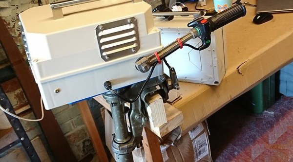
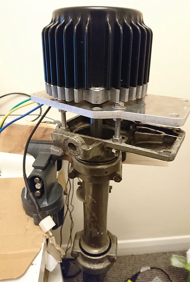
Once [Olly] had removed the old gas engine from the top of the outboard, he designed an adapter plate in OnShape and had it cut out of aluminum so he could mount a beefy 1 kW 48 V brushless electric motor in its place. Connecting the new electric motor to the carcass of the outboard actually ended up being simpler than putting the original motor on, as this time around he didn’t need to reconnect the cooling pumps which would usually pull water from down by the propeller and recirculate it through the engine.
While the mechanical aspects of this project are certainly cool, we’re especially interested in the control system for this newly electric outboard. It uses a 3.2 inch Nextion color touch screen and Arduino Nano to provide a very slick looking digital “dashboard” which can convey motor status and other information at a glance. Unfortunately, [Olly] says the details on that part of the project will be saved for a future post, leaving us with only a single picture of the system’s interface for us to drool over until then.
We’ve seen the occasional seafaring project that made use of an electric trolling motor, and we’ve even seen an electric drill put in some overtime spinning a prop in the water. Converting gasoline boat over to electric is however a rarity. But much like electric car conversions, such projects may become more common as the cost and complexity of powerful electric propulsion systems continues to fall.
[Thanks to Alex for the tip.]