This DIY Turntable Just Got Freaky Fresh

Photography turntables are made for both the precise and lazy. Whether you are concerned about the precision of consistent angles during a photo shoot or you simply do not want to stand there rotating a plate after every picture — yes, it does get old — a lazy susan style automatic photography turntable is the ticket. This automatic 360° design made over at circuito.io satisfies both of these needs in an understated package

The parts required to make this DIY weekend project are about as minimal as they get. An Arduino Uno controls it all with a rotary encoder for input and a character LCD to display settings. The turntable moves using a stepper motor and an EasyDriver. It even takes care of controlling the camera using an IR LED.

The biggest obstruction most likely to arise is creating the actual laser cut casing itself. The circuito team avoided this difficulty by using Pololu‘s online custom laser cutting service for the 4 necessary laser cut parts. After all of the components have been brought together, all that is left to do is Avengers assemble. They provide step by step instructions for this process in such a straightforward way that you could probably put this sucker together blindfolded.

We have seen some other inspired photography turntables on Hackaday before. [NotionSunday] created a true turntable hack based off of the eject mechanism of an old DVD-ROM drive. With the whole thing spinning on the head assembly of a VCR, this is the epitome of letting nothing go to waste. We also displayed another very similar Arduino Uno controlled turntable created 2 years ago by [Tiffany Tseng]. There is even a non-electronic version out there of a DIY 360° photography turntable that only uses a lazy susan and tape measure. All of these photography turntable hacks do the job wonderfully, but there was something that we liked about the clean feel of this one. All of the necessary code for this project has been provided over at GitHub. What is your favorite photography turntable?

Modernizing A 170 Year Old Antique Grandfather Clock

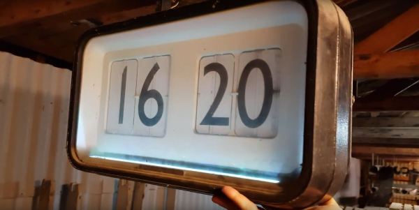
Frankly, we let out a yelp of despair when we read this in the tip line “Antique Grandfather clock with Arduino insides“! But before you too roll your eyes, groan, or post snark, do check out [David Henshaw]’s amazing blog post on how he spent almost eight months working on the conversion.

Before you jump to any conclusions about his credentials, we must point out that [David] is an ace hacker who has been building electronic clocks for a long time. In this project, he takes the antique grandfather clock from 1847, and puts inside it a new movement built from Meccano pieces, stepper motors, hall sensors, LEDs, an Arduino and lots of breadboard and jumper wires while making sure that it still looks and sounds as close to the original as possible.

He starts off by building a custom electro-mechanical clock movement, and since he’s planning as he progresses, meccano, breadboard and jumper wires were the way to go. Hot glue helps preserve sanity by keeping all the jumper wires in place. To interface with all of the peripherals in the clock, he decided to use a bank of shift registers driven from a regular Arduino Uno. The more expensive DS3231 RTC module ensures better accuracy compared to the cheaper DS1307 or similar clones. A bank of RGB LEDs acts as an annunciator panel inside the clock to help provide various status indications. The mechanical movement itself went through several iterations to get the time display working with a smooth movement of the hands. Besides displaying time, [David] also added a moon phase indicator dial. A five-rod chime is struck using a stepper motor driven cam and a separate solenoid is used to pull and release three chime hammers simultaneously to generate the loud gong sounds.

And here’s the amazing part – he did all of this before laying his hands on the actual grandfather clock – which was shipped to him in California from an antique clock specialist in England and took two months to arrive. [David] ordered just the clock housing, dial/face and external parts, with none of the original inner mechanism. Once he received it, his custom clock-work assembly needed some more tweaking to get all the positions right for the various hands and dials. A clock like this without its typical “ticktock” sound would be pretty lame, so [David] used a pair of solenoids to provide the sound effect, with each one being turned on for a different duration to produce the characteristic ticktock.

At the end of eight months, the result – christened Judge – was pretty satisfying. Check the video below to judge the Judge for yourself. If you would like to see some more of [David]’s clockwork, check out Dottie the Flip Dot Clock and A Reel to Reel Clock.

Continue reading “Modernizing A 170 Year Old Antique Grandfather Clock”

High Speed Chronograph Looks Like Pro Gear

It can be hard enough to take a good photograph of a running kid or pet, and if we’re being honest, sometimes even stationary objects manage to elude our focus. Now imagine trying to take a picture of something moving really fast, like a bullet. Trying to capture the moment a fast moving projectile hits an object is simply not possible with a human behind the shutter button.

Enter the ballistic chronometer: a device that uses a set of sensor gates and a highly accurate timer to determine how fast an object is flying through it. Chronometers that operate up to a couple hundred meters per second are relatively common, but [td0g] had something a little faster in mind. He’s come up with an optical setup that he claims can capture objects moving as fast as Mach 2. With this chronometer tied into a high-speed flash rig, [td0g] is able to capture incredible shots such as the precise instant a bullet shatters a glass of water.

Because he couldn’t find any phototransistors with the sub-microsecond response time necessary to detect a small object moving at 1,000 m/s, [td0g] ended up using LEDs in a photoconductive configuration, where 27 VDC is applied backwards against the diode. Careful monitoring of voltage fluctuations across the diode allows for detection of changes in the received light level. To cut down on interference, [td0g] used IR LEDs as his light sources, reasoning there would be less ambient IR than if he used something in the visual range.

What really impresses with this build is the attention to detail and amount of polish [td0g] put into the design. From the slick angled bracket that holds the Arduino and LCD to the 3D printed covers over the optical gates, the final device looks like a professional piece of equipment with a price tag to rival that of a used car.

For the future, [td0g] plans on upgrading to faster comparators than he LM339’s he has installed currently, and springing for professionally done PCBs instead of protoboard. In its current state this is already a very impressive piece of kit, so we’d love to see what it looks like when it’s “finished”.

If you don’t need something quite this high end but still would like to see how fast something is going, we have covered chronometer builds to fit every budget.

UV Sensitive Filament As A Persistent Display

Some of the hacks we feature are modifications of existing devices, others are ground-up builds of entirely new ones. And then there are the experiments, things that have to be worth trying because they just might work. In this final category we have [Matt]’s work with  UV sensitive plastic to form the basis of a simple persistent display, which has created something best described as a proof-of-concept that shows promise, and definitely proves that he had an idea very much worth trying.

The idea makes use of a plastic that changes colour from white to purple when exposed to UV light. He 3D printed a waffle-like structure to locate over a 3×3 grid of UV LEDs, which he could then illuminate under the control of an Arduino Mini Pro. A short illumination changes the colour of the plastic above it, creating a “pixel” that persists for several seconds. In this he has created a working proof of concept for a very simple 3×3 matrix display, albeit rather an unwieldy one. The advantage the idea offers is that a relatively long time of display can be achieved for a relatively short LED illumination, giving a potential for power saving.

The proof-of-concept itself isn’t particularly useful, but from this idea it’s possible a larger display could be practically made. An array of surface-mount LEDs could perhaps illuminate a larger array of plastic to a greater resolution, it’s definitely an idea that was worth trying, and which shows promise for further pursuit. If you’d like to see it in action he’s posted a video, which we’ve placed below the break.

Continue reading “UV Sensitive Filament As A Persistent Display”

Modern Technology For An Ancient Contest

Certamen is a special class of  high school quiz bowl tournament that’s focused solely on the classics. No, not Austen and Dickens, the actual classics. All the questions are about stuff like ancient Greek and Roman civilization and culture, classical mythology, and the finer points of Latin grammar. Like any other quiz bowl, the contestants use buttons to buzz in and answer the questions.

To win at Certamen, a team needs more than just a vast working knowledge of classical antiquity. They also have to be fast on the buzzer. The best way to do that is to practice with official equipment. But this is Hackaday, so you know what comes next: all the ones you can buy cost five times more than they should, so [arpruss] made an awesome open-source version for a fraction of the cost.

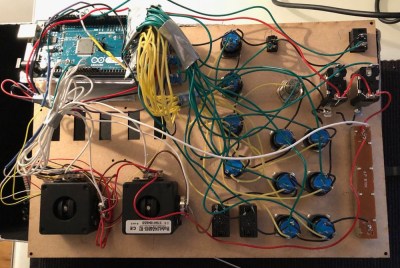
The practice machine consists of 12 arcade-style buttons connected to a control box. An Arduino Mega in the control box records the order of button presses as they arrive and displays a corresponding code on an LCD. A toggle switch selects between Certamen mode, where one button press locks out the rest of the team, and a Quiz mode with no lockout.

Our favorite thing about this build is the way [arpruss] took care of managing long cables, which was one of his main must-haves. The buttons are wired to the control box with Cat6 in three groups of four—one cable per table, one pair per chair. Our other favorite thing is the Easter eggs. Hold down the clear button on the control box when the system is booting and one of two things happens: either the buttons band together and turn into piano keys, or some Latin poetry appears on the screen.

[arpruss]’s 3D-printed buzzer bases look pretty slick. If Certamen practice ever starts to get out of hand, he might consider more robust packaging, like these Devo hat buttons.

Roll Your Own Arduino PWM

Most projects are built on abstractions. After all, few of us can create our own wire, our own transistors, or our own integrated circuits. A few months ago, [Julian Ilett] found a problem using the Arduino library for PWM. Recently, he revisited the issue and used his own PWM code to fix the problem. You can watch the video below.

Of course, neither the Arduino library nor [Julian’s] code is actually producing PWM. The Atmel CPU’s hardware is doing the work. The Arduino library gives you a wrapper called analogWrite — especially handy if you are not using an Atmel CPU where the same abstraction will do the same work. The issue arose when [Julian] broke the abstraction to invert the PWM output.

Continue reading “Roll Your Own Arduino PWM”

Automating A Bowl Feeder With Arduino

Search for “bowl feeder” on Hackaday and you’ll get nothing but automated cat and dog feeders. That’s a shame, because as cool as keeping your pets fed is, vibratory bowl feeders are cooler. If you’ve seen even a few episodes of “How It’s Made” you’re likely to have seen these amazing yet simple devices, used to feed and align small parts for automated assembly. They’re mesmerizing to watch, and if you’ve ever wondered how parts like the tiny pins on a header strip are handled, it’s likely a bowl feeder.

[John] at NYC CNC is building a bowl-feeder with Arduino control, and the video below takes us on a tour of the build. Fair warning that the video is heavy on the CNC aspects of milling the collating outfeed ramp, which is to be expected from [John]’s channel. We find CNC fascinating, but if you’re not so inclined, skip ahead to the last three minutes where [John] discusses control. His outfeed ramp has a slot for an optical sensor to count parts. For safety, the Arduino controls the high-draw bowl feeder through an external relay and stops the parts when the required number have been dispensed.

We know, watching someone use a $20,000 CNC milling station might seem overkill for something that could have been 3D printed, but [John] runs a job shop after all and usually takes on big industrial jobs. Or small ones, like these neat color-infill machine badges.

Continue reading “Automating A Bowl Feeder With Arduino”