[Xerxes3rd] works at a place where they raise reptiles in terrariums. Such enclosures require controlled lighting, temperature and humidity. Humidity is maintained using “misting” devices. These are usually water containers with a pump whose outlet ends in a series of very fine spray nozzles which create the mist. A timer controls the pump’s on and off cycles.
[Xerxes3rd] purchased an Exo Terra Monsoon RS400 misting system – a low-cost misting device and soon discovered that it had a serious design flaw. The built-in timer malfunctions, and it mists a hundred times more than it should! A lot of folks who buy a product and discover it has an inherent design flaw will return it back for a refund. Instead, [Xerxes3rd] decided to break in and fix it instead – “warranty void if tampered” be damned.
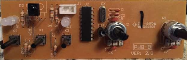
To start with, he needed to figure out what the problem was. He went about it in clinical fashion, eventually creating a slick document (PDF) outlining his observations and diagnosis. The timer controller board has a PIC micro, some buttons, potentiometers, LED’s and an IR receiver. The misting cycles are set using the two potentiometers – Off time and On time for the pump. His analysis and resolution makes for interesting reading.
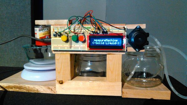
What he found was that the PIC micro was reading inconsistent values from the potentiometers. More specifically, the software isn’t doing any smoothing on the analog values it reads from the potentiometers. Since the PIC that controls the system wasn’t easily re-programmable, he opted to replace it with an Arduino Nano. At the same time, he got rid of the potentiometers that were used to set the misting frequency and duration, and added a 16×2 LCD. Time setting is now done using the three on board buttons. He removed the PIC micro and replaced it with two female header sockets, onto which he plugged a small board containing an Arduino Nano and a few components. He also cut the original PCB in half, removing the potentiometers and crystal oscillator in order to make room for the 16×2 character LCD.
The lizards are now probably thanking him for their perfectly timed doses of moisture. Having done this, he could probably add in more features such as a temperature-humidity sensor, a water level sensor or maybe even throw in an ESP8266 module and have the Lizards tweet when they need to be hydrated. Because that’s another thing hackers love – feature creep.


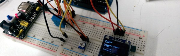
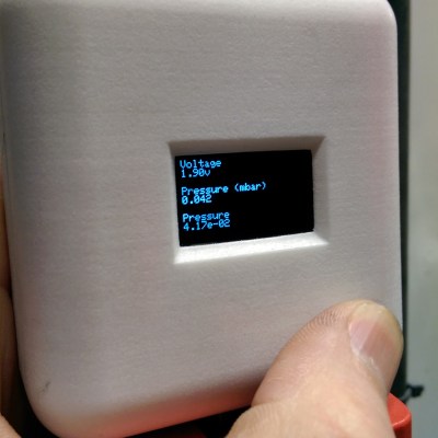 This project goes a little beyond simple Arduino programming though. A 12V to 5V power supply drives the device, which is laid out on a blank PCB. The display fits snugly over the circuit which reduces the footprint of the project, and the entire thing is housed in a custom-printed case with a custom-printed pushbutton. The device gets power and data over the RJ45 connection so no external power is needed. If you want to take a look at the code,
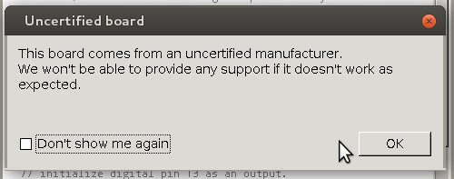 But before that, it’s time to bid farewell to the cheeky little popup window that would deliver a warning message when using a board bearing the USB IDs of their former-partner-turned-competitor. We absolutely