Motorcyclists are paranoid about being hit by cars, and with reason. You’re a lot safer when you’re encased in a metal shell, with airbags and seatbelts. The mass difference between a car and a motorcycle doesn’t work out well for the biker, either. Unfortunately for bikers, motorcycles are also slimmer and generally less visible than cars.
A few decades ago, motorcycle manufacturers switched over to daytime running headlights to make bikes more visible. In the meantime, however, cars have done the same, leading many bikers to fear that their visibility advantage is losing it’s impact. The solution? Blink the headlights gently during the daytime, and run them normally at night.
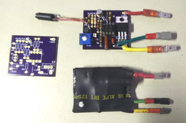
[William Dudley] was unsatisfied with commercial versions, so he built a custom headlight modulator for his motorcycle.
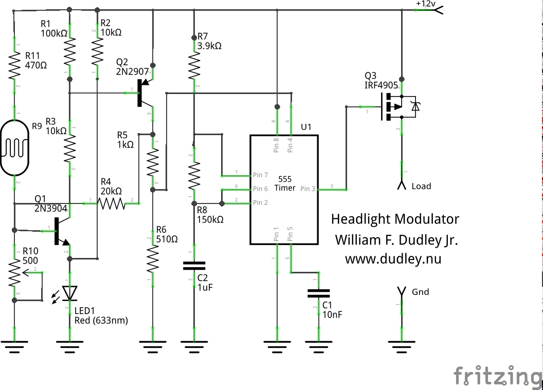 And believe it or not, he did it with a 555 timer IC and a light-dependent resistor (plus some transistors and a whole slew of miscellaneous parts). But [William]’s design is a good one, and he walks you through all of the choices he made in building the light-sensing circuit that disables the 555.
Whether you need a motorcycle headlight modulator or are interested to learn how this problem would be solved in the pre-Arduino days, go check out [William]’s post. And while you’re on the nostalgic electronics trip, check out this nixie tube speedometer.