Today, if you want to get a picture from your oscilloscope — maybe to send to a collaborator or to stick in a document or blog post — it is super easy. You can push an image to a USB stick or sometimes even just use the scope’s PC or web interface to save the picture directly to your computer. Of course, if it is on the computer, you could use normal screen capture software. But that hasn’t always been the case. Back in the days when scopes were heavy and expensive, if you wanted to capture an image from the tube, you took a picture. While you might be able to hold up your camera to the screen, they made specific cameras just for this purpose.
Before flat screen technologies took over, we associate TV with the CRT. But there were other display technologies that worked, they just weren’t as practical. One scheme was the Nipkow disk, and [Bitluni] decided to build a working demonstration of how such a system works.
Essentially, there’s a spinning disk with a spiral pattern of holes in it. As the disk spins, a light behind it turns on or off. If you time everything right, you get an image that can move. This particular model uses stepper motors, which is a bit of a modern concession.
The result was actually much better than you might guess, but a far cry from a modern display device, of course. The screen material needed a little tweaking, but even the initial results were very impressive. If this were trying to be practical, it would probably require a bit more work on the light source and screen.
Interestingly, the Nipkow disk arrangement was just as suitable for scanning as displaying. Instead of a light behind the wheel, you simply used a light sensor. Of course, in practice, getting everything synchronized and mass-producing high-resolution sets would have been a tremendous challenge a century ago.
[David Shadoff] has a clear soft spot for the NEC console systems and has been collecting many tools and data about them. When developing with these old systems, having a way to upload code quickly is a real bonus, hence the creation of the PC-FX Dev Cart. Based on the Raspberry Pi RP2040, the custom cartridge PCB has everything needed to run software uploadable via a USB-C connection.
While the PC-FX is a CDROM-based system, it does sport a so-called FX-BMP or backup memory port cartridge slot, which games can use to save state and perform other special functions. Under certain circumstances, the PC-FX can be instructed to boot from this memory space, and this cartridge project is intended to enable this. Having a quick way to upload and execute code is very useful when exploring how these old systems work, developing new applications, or improving the accuracy of system emulators. The original FX-BMP cartridge has little more inside than a supercapacitor-backed SRAM and a custom interfacing IC, and of course, it would be quite a hassle to use this to develop custom code.
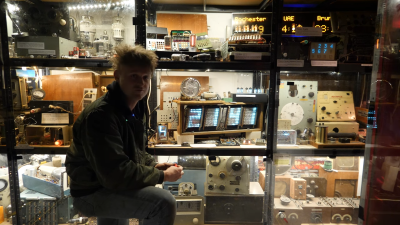
[Sam Battle] is no stranger to these pages, nor is his Museum is not Obsolete. The museum was recently gifted an enormous Nixie tube created by Dalibor Farný, a B-grade (well, faulty) unit that could not be used in any of their commissioned works but was perfectly fine for displaying in the museum’s retro display display. This thing is likely the largest Nixie tube still being manufactured; although we read that it’s probably not the largest ever made, it’s still awesome.
Every hacker should have their own museum.
It is fairly simple to use, like all Nixie tubes, provided you’re comfortable with relatively high DC voltages, albeit at a low current. They need a DC voltage because if you drive the thing with AC, both the selected cathode digit plate and the anode grid will glow, which is not what you need.
Anyway, [Sam] did what he does best, clamped the delicate tube in some 3D printed mounts and hooked up a driver made from stuff he scraped out of a bin in the workshop. Obviously, for someone deeply invested in ancient electromagnetic telephone equipment, a GPO (British General Post Office, now BT) uniselector was selected, manually advanced with an arcade-style push button via a relay. This relay also supplies the ~140 V for the common anode connection on the Nixie tube. The individual digit cathodes are grounded via the uniselector contacts. A typically ancient GPO-branded snubber capacitor prevents the relay contacts from arcing over and ruining the display unit. There isn’t much more to it, so if you’re in the Ramsgate, UK, area anytime soon, you can pop in and play with it for yourself.
Over at the University of Wisconsin’s Undergraduate Projects Lab (UPL) there’s been a way to check whether this room is open for general use by CS undergraduates and others practically for most of the decades that it has existed. Most recently [Andrew Moses] gave improving on the then latest, machine vision-based iteration a shot. Starting off with a historical retrospective, the 1990s version saw a $15 camera combined with a Mac IIcx running a video grabber, an FTP server and an HP workstation that’d try to fetch the latest FTP image.
As the accuracy of this system means the difference between standing all forlorn in front of a closed UPL door and happily waddling into the room to work on some projects, it’s obvious that any new system had to be as robust as possible. The machine vision based version that got installed previously seemed fancy: it used a Logitech C920 webcam, a YOLOv7 MV model to count humanoids and a tie into Discord to report the results. The problem here was that this would sometimes count items like chairs as people, and there was the slight issue that people in the room didn’t equate an open door, as the room may be used for a meeting.
Thus the solution was changed to keeping track of whether the door was open, using a sensor on the two doors into the room. Sadly, the captive-portal-and-login-based WiFi made the straightforward approach with a reed sensor, a magnet and an ESP32 too much of a liability. Instead the sensor would have to communicate with a device in the room that’d be easier to be updated, ergo a Zigbee-using door sensor, Raspberry Pi with Zigbee dongle and Home Assistant (HA) was used.
One last wrinkle was the need to use a Cloudflare-based tunnel add-on to expose the HA API from the outside, but now at long last the UPL door status can be checked with absolute certainty that it is correct. Probably.
Featured image: The machine vision-based room occupancy system at UoW’s UPL. (Credit: UPL, University of Wisconsin)
[Sebastian Mihai] is a prolific programmer and hacker with a particular focus on retrocomputing and period games, and this latest hack, adding new gameplay elements to Capcom’s Street Fighter II – Champion Edition, is another great one. [Sebastian] was careful to resist changing the game physics, as that’s part of what makes this game ‘feel’ the way it does, but added some fun extra elements, such as the ability to catch birds, lob barrels at the other player, and dodge fire.
It’s likely that many Hackaday readers will have had their interest in electronics as a child honed by exposure to an electronics kit. The type of toy that featured a console covered in electronic components with spring terminals, and on which a variety of projects could be built by wiring up circuits. [Matthew North Music] has a couple of these, and he’s made a video investigating whether they can be used to make music.
The kits he’s found are a Radio Shack one from we’re guessing the 1970s, and a “Cambridge University Recording Studio” kit that looks to be 1990s-vintage. The former is all discrete components and passive, while the latter sports that digital audio record/playback chip that was the thing to have in a novelty item three decades ago. With them both he can create a variety of oscillator and filter circuits, though for the video he settles for a fairly simple tone whose pitch is controlled by an light-dependent resistor, and a metronome as a drum beat.
The result is a little avant garde, but certainly shows promise. The beauty of these kits is they can now be had for a song, and as grown-ups we don’t have to follow the rules set out in the book, so we can see there’s a lot of fun to be had. We look forward to some brave soul using them in a life performance at a hacker camp. Continue reading “75-In-One Music”→