
You have an old radio — in the case of [The Radio Mechanic], a Stromberg Carlson — and it needs new knobs. What do you do? You can’t very well pop down to the local store and find any knobs anymore. Even if you are lucky enough to be around an electronics store, they aren’t going to have knobs to do justice to an antique radio. You could 3D print them, of course, but there are a number of issues with transferring the old knob to a CAD file for printing. So [The Radio Mechanic] decided to cast them instead.
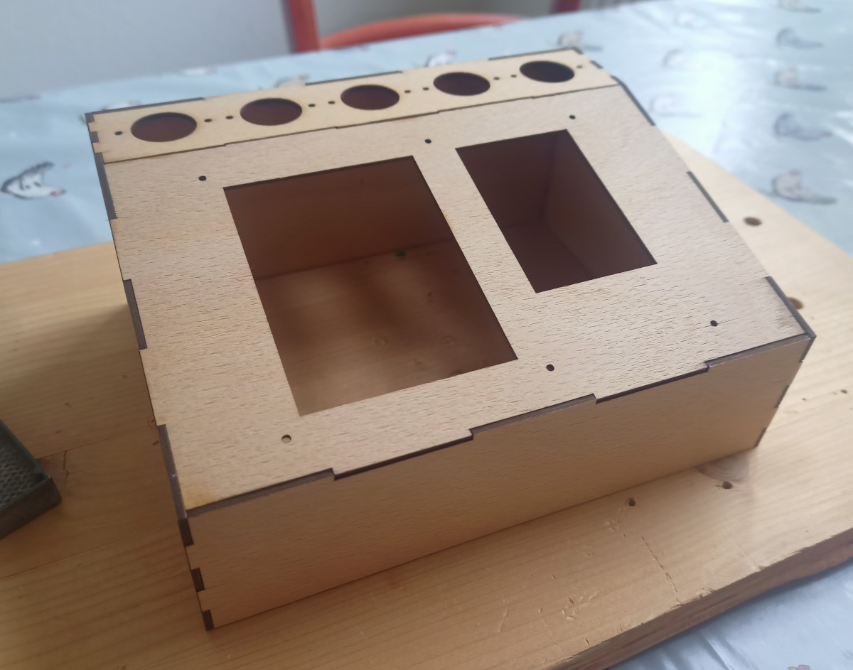
He printed some fixtures to help with the molding using two-part molding silicone. He mounted the knob on a shaft in a jig, filled the jig with silicone, and lowered the knob into the mix. The next day, he had a good-looking mold.
The next step, of course, is to cast with resin. Admittedly 3D printing would have been faster, but would not have as nice a surface finish. The epoxy resin is clear, but he was hopeful that some caramel pigment would match the original knob color. Spoiler alert: it didn’t. The resulting knob looked translucent, like a root beer barrel candy, rather than the brown sugar color of the original knob.
The knob needed a spring insert to hold the shaft, so he repurposed some from a different kind of radio. Overall, this is the kind of thing we always think we are going to do when we need something and then we rarely follow through. Then again, we rarely have the patience to wait as long as these two knobs took to make.
Of course, a casting guerrilla doesn’t have to make just knobs. You can even add metal powders to do cold metal casting.


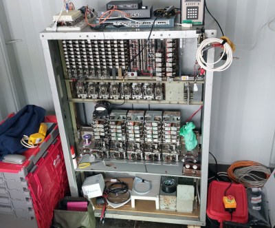 It stood at the back of the container, with a row of four telephones in front of it. We particularly liked the angular “Trimphone”, the height of 1960s and 70s chic. You could dial the other phones in the network with a two digit number, and watch the exchange clicking in the background as you did so. Some of the sounds weren’t quite the same as the full-sized equivalents, with the various tones being replaced by vibrating reeds.


