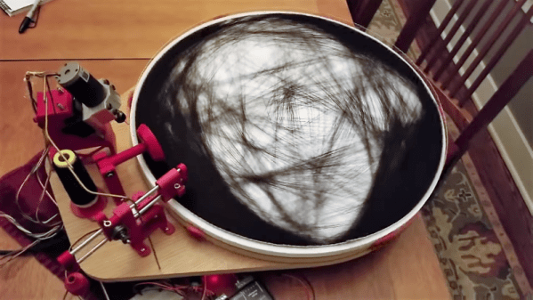
We have semi-fond memories of string art from our grade school art class days. We recall liking the part where we all banged nails into a board, but that bit with wrapping the thread around the nails got a bit tedious. This CNC string art machine elevates the art form far above the grammar school level without all the tedium.
Inspired by a string art maker we recently feature, [Bart Dring] decided to tackle the problem without using an industrial robot to dispense the thread. Using design elements from his recent coaster-creating polar plotter, he built a large, rotating platform flanked by a thread handling mechanism. The platform rotates the circular “canvas” for the portrait, ringed with closely spaced nails, following G-code generated offline. A combination of in and out motion of the arm and slight rotation of the platform wraps the thread around each nail, while rotating the platform pays the thread out to the next nail. Angled nails cause the thread to find its own level naturally, so no Z-axis is needed. The video below shows a brief glimpse of an additional tool that seems to coax the threads down, too. Mercifully, [Bart] included a second fixture to drill the hundreds of angled holes needed; the nails appear to be inserted manually, but we can think of a few fixes for that.
We really like this machine, both in terms of [Bart]’s usual high build-quality standards and for the unique art it creates. He mentions several upgrades before he releases the build files, but we think it’s pretty amazing as is.
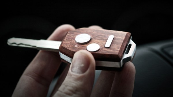
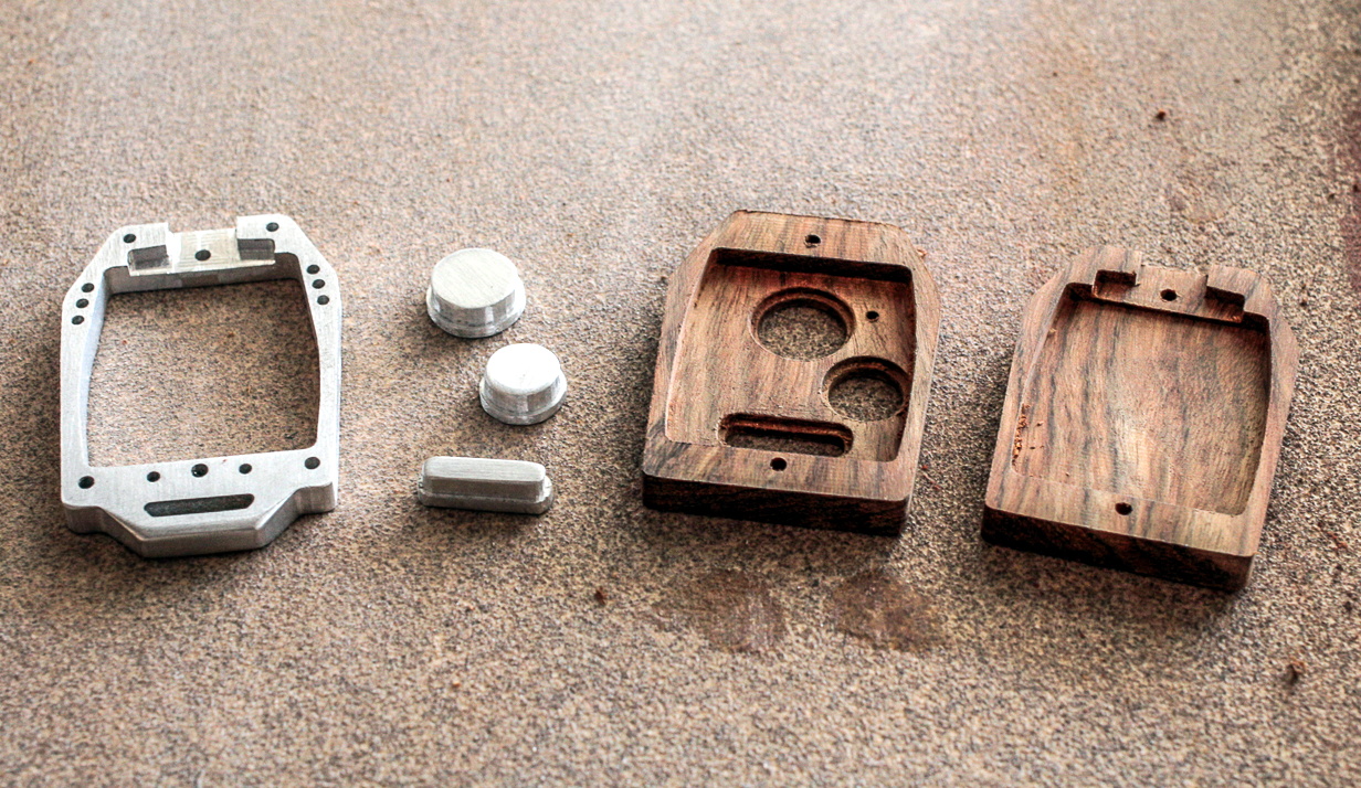
Now that nearly every car on the road comes with an electronic key fob, people are desperate to find ways to repair these indispensable little gadgets without coughing up potentially hundreds of dollars at the dealership. There’s a whole market for replacement shells which you can transplant your (hopefully) still functional electronics into, but if you’re going to go through the trouble of putting the electronics into a new case, why not make it special?
That’s what [Michicanery] was thinking when he decided to build his own custom key fob. The end result is an utterly magnificent feat of engineering that’s sure to be a conversation for the life of the vehicle, if not beyond. Made of wood and aluminum cut on his OpenBuilds Lead CNC 1010, this build just might inspire you to “accidentally” drop your existing fob from a great height. Oh no, what a shame.
[Michicanery] starts by disassembling his original fob, which is the type that has a key integrated directly into the device. This meant his replacement would need a bit more thought put into it than a separate stand-alone fob, but at least it wasn’t one of the ones where you have to stick the whole thing into the dashboard. To make sure the build was strong enough to survive a lifetime of being turned in the ignition and generally fiddled with, he cut the central frame and buttons out of 1/4″ thick aluminum.
The top and bottom of the fob were then cut from Chechen wood and then chamfered on a table router so it felt a bit better in the hand. He applied oil to the pieces to bring out the natural color and grain of the wood, but not before engraving his own logo onto the back of the case for that extra touch of personalization. Not that we think [Michicanery] is going to have trouble identifying his keys from this point on.
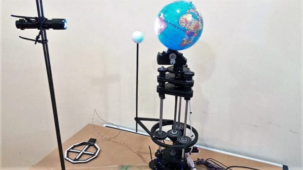
Kids – they’re such a treasure. One minute you’re having a nice chat, the next minutes they’re testing your knowledge of the natural world with a question like, “Why can we see the Moon during the day?” And before you know it, you’re building a CNC Earth-Moon orbital model.
We’ve got to applaud [sniderj]’s commitment to answering his grandson’s innocent question. What could perhaps have been demonstrated adequately with a couple of balls and a flashlight instead became an intricate tellurion that can be easily driven to show the relative position of the Earth and Moon at any date; kudos for anticipating the inevitable, “Where was the moon when I was born, Grampa?” question. The mechanism is based on the guts of a defunct 3D-printer, with the X-, Y-, and Z-axis steppers now controlling the Earth’s rotation and tilt and the Moon’s orbit respectively, with the former extruder drive controlling the tilt of the Moon’s orbital plane. A complex planetary gear train with herringbone gears, as well as a crossed-shaft helical gear set, were 3D-printed from PLA. The Earth model is a simple globe and the Moon is a ping-pong ball; [sniderj] is thinking about replacing the Moon with a 3D-printed bump-map model, a move which we strongly endorse. The video below shows the tellurion going through a couple of hundred years of the saros at warp speed.
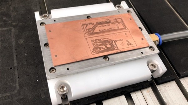
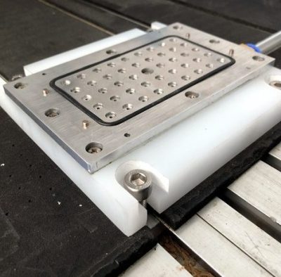
CNC milling a copper-clad board is an effective way to create a PCB by cutting away copper to form traces instead of etching it away chemically, and [loska] has improved that process further with his DIY PCB vacuum table. The small unit will accommodate a 100 x 80 mm board size, which was not chosen by accident. That’s the maximum board size that the free version of Eagle CAD will process.
When it comes to milling PCBs, double-sided tape or toe clamps are easy solutions to holding down a board, but [loska]’s unit has purpose behind its added features. The rigid aluminum base and vacuum help ensure the board is pulled completely flat and held secure without any need for external fasteners or adhesives. It’s even liquid-proof, should cutting fluid be used during the process. Also, the four raised pegs provide a way to reliably make double-sided PCBs. By using a blank with holes to match the pegs, the board’s position can be precisely controlled, ensuring that the back side of the board is cut to match the front. Holes if required are drilled in a separate process by using a thin wasteboard.
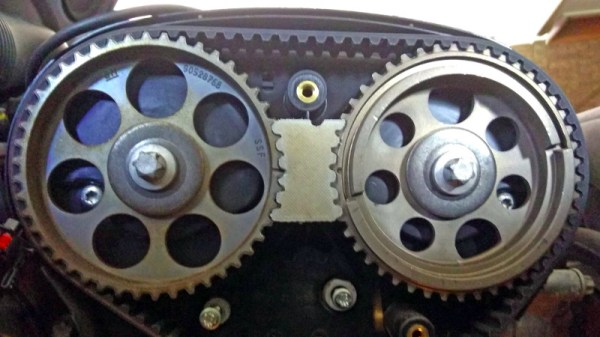
The modern overhead-cam internal combustion engine is a mechanical masterpiece of hundreds of parts in perfect synchronisation. In many cases it depends for that synchronisation upon a flexible toothed belt, and those of you who have replaced one of these belts will know the exacting requirements for keeping the various pulleys in perfect alignment during the process.
[Greolt] had this problem with a dual overhead-cam engine, particularly that the shafts would spring out of alignment on removal of the belt. The solution was one of those beautifully simple hacks that use high-tech methods to make something that is not high-tech in itself but which solves a problem perfectly. He produced a CNC-machined block of HDPE to sit between the two toothed pulleys that was machined exactly to their profiles and which once inserted kept them securely and exactly in alignment.
It’s likely that the same job could easily be done with a 3D printer, and indeed we’ve seen it done with a small piece of soft wood and a hammer. But there is something very elegant indeed about this particular incarnation that we like, it may not be the most complex of the hacks you’ll see here but we’re sure you’ll agree if you’ve ever changed a cambelt, it’s a pretty useful one.
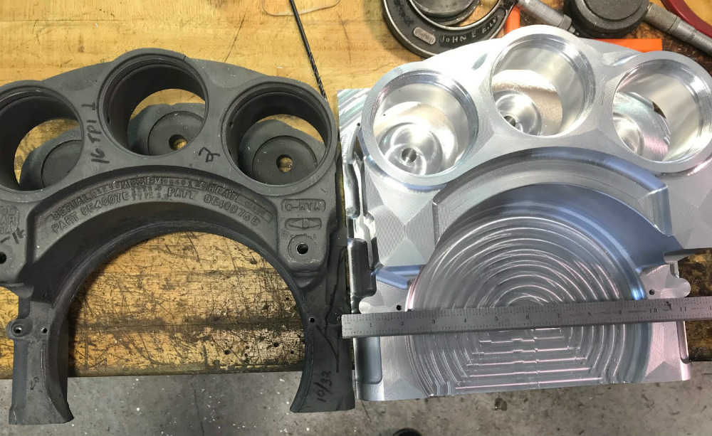
Towards the end of the Second World War, as the United States considered their options for a possible invasion of Japan, there was demand for a new fighter that could escort long range bombers on missions which could see them travel more than 3,200 kilometers (2,000 miles) without refueling. In response, North American Aviation created the F-82, which essentially took two of their immensely successful P-51 fighters and combined them on the same wing. The resulting plane, of which only 272 were built, ultimately set the world record for longest nonstop flight of a propeller-driven fighter at 8,129 km (5,051 mi) and ended up being the last piston engine fighter ordered by the United States Air Force.
The project provides a fascinating look at what it takes to not only return a 70+ year old ultra-rare aircraft to fully functional status, but do it in a responsible and historically accurate way. With only four other intact F-82’s in the world, replacement parts are obviously an exceptional rarity. The original parts used to rebuild this particular aircraft were sourced from literally all over the planet, piece by piece, in a process that started before [Tom] even purchased the plane itself.
In a way, the search for parts was aided by the unusual nature of the F-82, which has the outward appearance of being two standard P-51 fighters, but in fact utilizes a vast number of modified components. [Tom] would keep an eye out for parts being sold on the open market which their owners mysteriously discovered wouldn’t fit on a standard P-51. In some cases these “defective” P-51 parts ended up being intended for the Twin Mustang project, and would get added to the collection of parts that would eventually go into the XP-82 restoration.
For the parts that [Tom] couldn’t find, modern manufacturing techniques were sometimes called in. The twin layout of the aircraft meant the team occasionally had one component but was missing its counterpart. In these cases, the original component could be carefully measured and then recreated with either a CNC mill or 3D printed to be used as a die for pressing the parts out of metal. In this way the team was able to reap the benefits of modern production methods while still maintaining historical accuracy; important on an aircraft where even the colors of the wires used in the original electrical system have been researched and faithfully recreated.
We’ve seen plenty of restorations here at Hackaday, but they tend to be of the vintage computer and occasionally Power Wheels variety. It’s interesting to see that the same sort of techniques we apply to our small scale projects are used by the pros to preserve pieces of history for future generations.
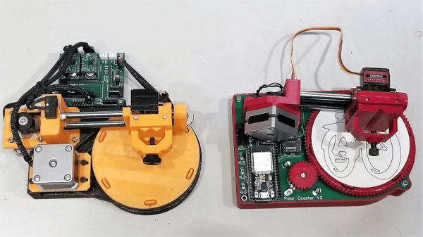
If you’re anything like us, your success with the opposite sex at the bar wasn’t much to brag about. But imagine if you had only had this compact CNC polar plotter and could have whipped up a few custom coasters for your intended’s drink. Yeah, that definitely would have helped.
Or not, but at least it would have been fun to play with. This is actually an improved version of [bdring]’s original “Polar Coaster”. Version 2 is really just a more compact and robust version of the original. The new one has a custom controller for the steppers and pen-lift servo, and everything is mounted neatly to the main PCB. Where the original used a timing belt to drive the platter, the new one uses 3D-printed helical gears, and the steppers have been replaced by slimmer motors. It even has an SD card and smartphone UI, and the coasters look pretty good.
There’s no video of the new one, but you can see its predecessor in action below and imagine the possibilities. Snap a picture and have a line art rendition of someone plotted while you’re waiting for drinks? Just remember not to take any laser engraved wooden nickels.