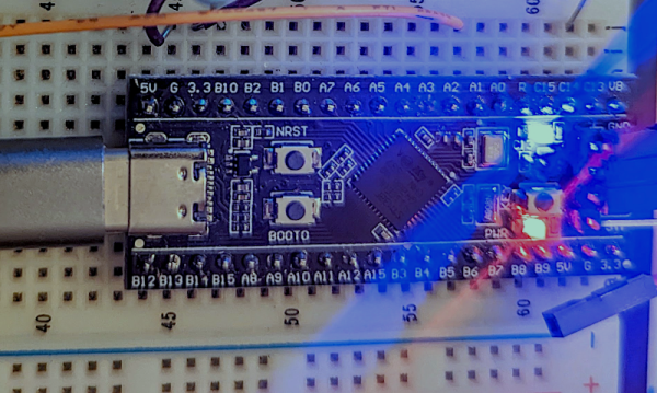
We see tons of projects with the infamous “Blue Pill” STM32 boards. They are cheap and plentiful and have a lot of great features, or at least they were before the chip shortage. I recently picked up a “Black Pill”, which is very similar but has an even more powerful processor. For a few bucks, you get an ARM CPU that can run at 100 MHz (but with USB, probably 96 MHz). There’s 512 kB of flash and 128 kB of RAM. There’s a USB type C port, and even a button and an LED onboard. The thing fits on a breadboard and you can program it with a cheap STLink dongle which costs about $10.
Of course, you then have to consider the software. The STM32Cube stuff is a lot to set up and learn but it does let you do just about anything you can imagine. Then there is the STM32Duino plug-in that lets you use it as a beefy Arduino. That works and is easy enough to set up. However, there’s also Mbed. The only problem is that Mbed doesn’t work right out of the box. Turns out, though, it isn’t that hard to set up. I’ll show you how easy it is to get things going and, next time, I’ll show you a practical example of a USB peripheral that uses the mBed RTOS features.
First Steps
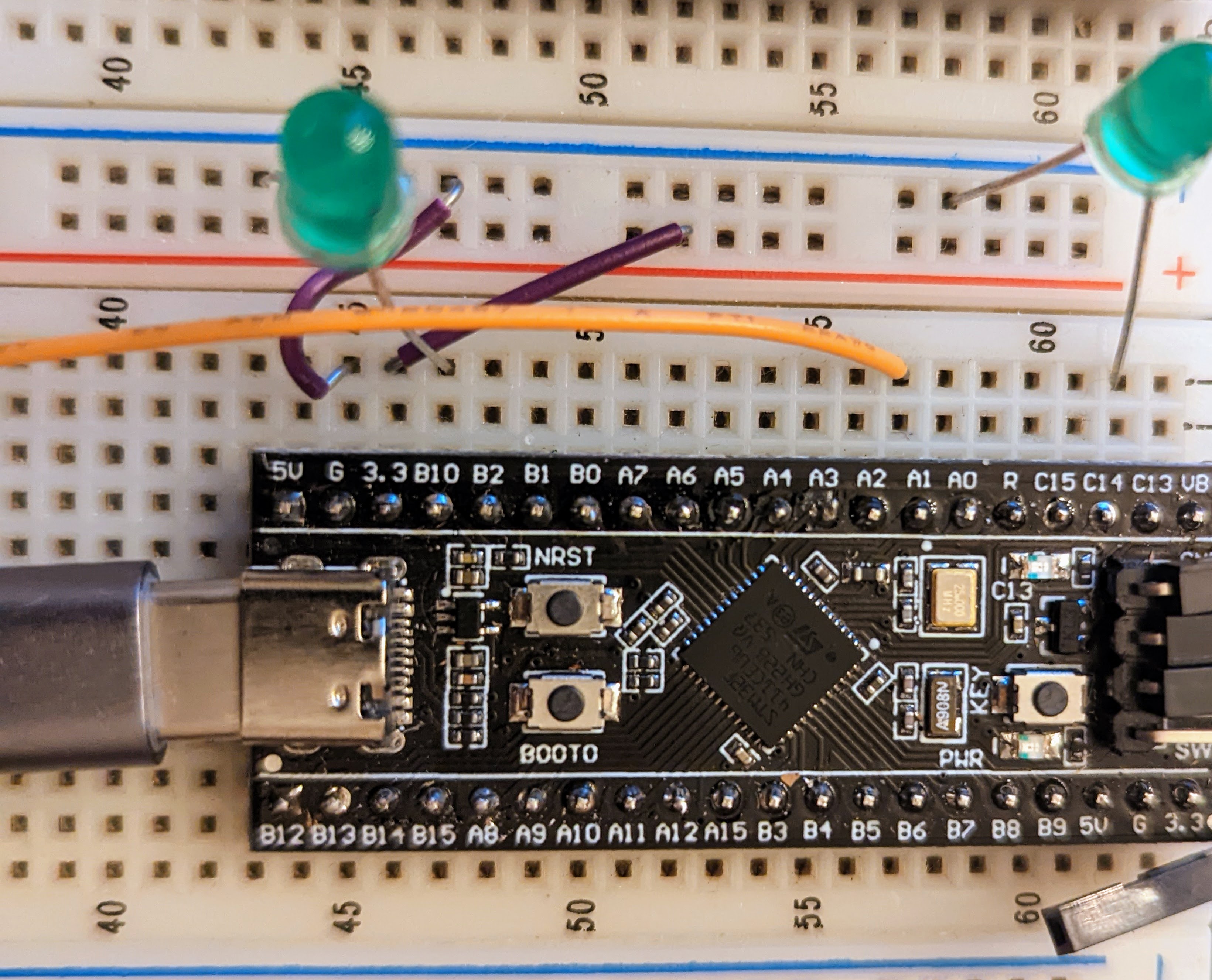
Obviously, you are going to need a Black Pill. There are at least two choices but for as cheap as they are there is little reason not to get the STM32F411 version that has more memory. The DIP form factor will fit in whatever breadboard you happen to have and a USB C cable will power the board so unless you are driving a lot of external circuitry, you probably don’t need an external supply.