Knitting ALUs (and Flipdots)

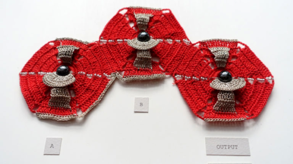
[Irene Posch] is big into knitted fabric circuits. And while most of the textile circuits that we’ve seen are content with simply conducting enough juice to light an LED, [Irene]’s sights are set on knittable crafted arithmetic logic units (ALUs). While we usually think of transistors as the fundamental building-blocks of logic circuits, [Irene] has developed what is essentially a knit crochet relay. Be sure to watch the video after the break to see it in construction and in action.

The basic construction is a coil of conductive thread that forms an electromagnet, and a magnetic bead suspended on an axle so that it can turn in response to the field. To create a relay, a flap of knit conductive thread is attached to the bead, which serves as the pole for what’s essentially a fabric-based SPDT switch. If you’ve been following any of our relay-logic posts, you’ll know that once you’ve got a relay, the next step to a functioning computer is a lot of repetition.

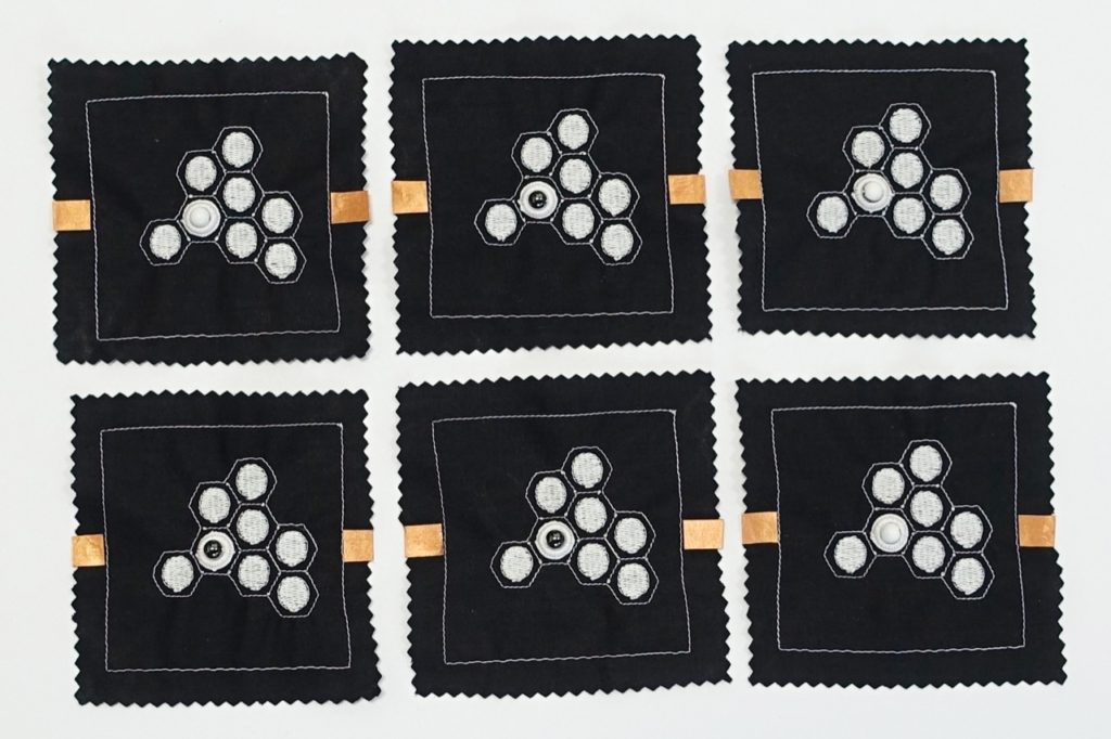
How does [Irene] plan to display the results of a computation? On knit-and-bead flipdot displays, naturally. Combining the same electromagnet and bead arrangement with beads that are painted white on one side and black on the other yields a human-readable one-bit display. We have an unnatural affinity for flipdot displays, and making the whole thing out of fabric-store components definitely flips our bits.

Anyway, [Irene Posch] is a textile-tech artist who you should definitely be following if you have any interest in knittable computers. Have you seen anything else like this? Thanks [Melissa] for the awesome tip!

Continue reading “Knitting ALUs (and Flipdots)”

Single Board Relay Computer

We all know you can build a computer out of relays, and if you’re a regular reader of Hackaday, you’ve probably seen a few. Actually designing and fabricating a computer built around relays is another thing entirely, and an accomplishment that will put you right up there with the hardware greats.

The newest inductee of the DIY microcomputer hall of fame is [Jhallen]. He’s built a microcomputer ‘trainer’ out of relays. It’s got more click and clack than the Tappet family, and is a work of art rendered in DPDT relays.

The biggest consideration in designing a relay computer is the memory. You can implement a CPU in a few dozen relays, but even a small amount of memory is still hundreds of additional components. In this computer, [Jhallen] is sort of cheating. The memory is implemented as 256 32-bit words on a microcontroller alongside a controller for the front panel. The CPU is still all relays, with support for self-modifying code, a bunch of instructions for conditional jumps, and an ‘increment and jump if not equal to zero’ instruction.

Below, you can check out a very in-depth video of the relay computer in action, starting off with some satisfying click and clack of Euclid’s algorithm and a demonstration of the variable clock rate. The video goes on to demonstrate the assembly language of the relay computer itself and a bit of the overall architecture. This is really one of the most educational demo videos for vintage computing we’ve ever seen.

[Jhallen] assembled a few of these boards and he’s selling some of the extras. If you have $600, you can pick one up over on Tindie (standard Hackaday / Tindie disclosure statement). Considering the amount of soldering required to assemble this board, we’re going to guess that’s a very fair price.
Continue reading “Single Board Relay Computer”

Breadboarding With E-Paper

[David Watts] picked up an inexpensive Waveshare e-Paper display. He made a video about using it with a breadboard, and you can see it below.

The E-Paper or E-Ink displays have several advantages. They are low power, they retain their display even without power, and they are very visible in direct light. The downside is they don’t update as fast as some other display technologies.

Continue reading “Breadboarding With E-Paper”

A Noob’s Guide To McMaster-Carr

For the penny-pinching basement hacker, McMaster-Carr seems like a weird go-to resource for hardware. For one, they’re primarily a B2B company; and, for two, their prices aren’t cheap. Yet their name is ubiquitous among the hacker community. Why? Despite the price, something makes them too useful to ignore by everyday DIY enthusiasts. Those of us who’ve already been enlightened by the McMaster-Carr can design wonders with a vocabulary of parts just one day away at the click of a button.

Today, this article is for those of us who have yet to receive that enlightenment. When used wisely, this source of mechanical everything brings us a world of fast parts at our fingertips. When used poorly, we find nothing but overpriced stock components in oversized shipping boxes.

Since we, the McMaster-Carr sages, are forever doomed to stuff our desk drawers with those characteristic yellow baggies till the end of time, we thought we’d give an intro to the noobs that are just beginning to flex their muscles with this almighty resource. Grab another cup of coffee as we take you on a tour of the good and good-grievances of McMaster-Carr.

Continue reading “A Noob’s Guide To McMaster-Carr”

The Components Are INSIDE The Circuit Board

Through-hole assembly means bending leads on components and putting the leads through holes in the circuit board, then soldering them in place, and trimming the wires. That took up too much space and assembly time and labor, so the next step was surface mount, in which components are placed on top of the circuit board and then solder paste melts and solders the parts together. This made assembly much faster and cheaper and smaller.

Now we have embedded components, where in order to save even more, the components are embedded inside the circuit board itself. While this is not yet a technology that is available (or probably even desirable) for the Hackaday community, reading about it made my “holy cow!” hairs tingle, so here’s more on a new technology that has recently reached an availability level that more and more companies are finding acceptable, and a bit on some usable design techniques for saving space and components.

Continue reading “The Components Are INSIDE The Circuit Board”

Bodging On More Flash Memory

[Curmudegeoclast] found himself running out of flash memory on a Trinket M0 board, so he decided to epoxy and fly-wire a whopping 2 MB of extra flash on top of the original CPU.

We’ll just get our “kids these days” rant out of the way up front: the stock SAMD21 ARM chip has 256 kB (!) of flash to begin with, and is on a breakout board with only five GPIO pins, for a 51 kB / pin ratio! And now he’s adding 2 MB more? That’s madness. The stated reason for [Curmudegeoclast]’s exercise is MicroPython, which takes up a big chunk of flash just for the base language. We suspect that there’s also a fair amount of “wouldn’t it be neat?” in the mix as well. Whatever.

The hack is a classic. It starts off with sketchy wires soldered to pins and breadboarded up with a SOIC expander board. Following that proof of concept, some degree of structural integrity is brought to the proceedings by gluing the flash chip, dead-bug, on top of the microcontroller. We love the (0805?) SPI pullup resistor that was also point-to-point soldered into place. We would not be able to resist the temptation to entomb the whole thing in hot glue for “long-term” stability, but there are better options out there, too.

This hack takes a minimalist board, and super-sizes it, and for that, kudos. What would you stuff into 2 MB of free flash on a tiny little microcontroller? Any of you out there using MicroPython or CircuitPython care to comment on the flash memory demands? 256 kB should be enough for anyone.

Sparkfun’s Alternate Reality Hardware

SparkFun has a new wing of hardware mischief. It’s SparkX, the brainchild of SparkFun’s founder [Nate Seidle]. Over the past few months, SparkX has released breakout boards for weird sensors, and built a safe cracking robot that got all the hacker cred at DEF CON. Now, SparkX is going off on an even weirder tangent: they have released The Prototype. That’s actually the name of the product. What is it? It’s a HARP, a hardware alternate reality game. It’s gaming, puzzlecraft, and crypto all wrapped up in a weird electronic board.

The product page for The Prototype is exactly as illuminating as you would expect for a piece of puzzle electronics. There is literally zero information on the product page, but from the one clear picture, we can see a few bits and bobs that might be relevant. The Prototype features a microSD card socket, an LED that might be a WS2812, a DIP-8 socket, a USB port, what could be a power switch, a PCB antenna, and a strange black cylinder. Mysteries abound. There is good news: the only thing you need to decrypt The Prototype is a computer and an open mind. We’re assuming that means a serial terminal.

The Prototype hasn’t been out for long, and very few people have one in hand. That said, the idea of a piece of hardware sold as a puzzle is something we haven’t seen outside of conference badges. The more relaxed distribution of The Prototype is rather appealing, and we’re looking forward to a few communities popping up around HARP games.