Aviation consists of two major groups. Airplane enthusiasts, and helicopter enthusiasts. The two groups rarely get along, each extolling the virtues of their chosen craft. Somewhere in between are autogyro folks. People who like vehicles that blend the best (or worst) of both airplanes and helicopters. Aviation master [Peter Sripol] has dipped his toes into the autogyro world, but not without some trouble.
Autogyros are propelled by a propeller, like a plane. They also have a tail section that works similar to a fixed-wing aircraft. That’s where the similarities end though. Lift for autogyros comes in the form of a rotating set of blades, much like a helicopter. Autogyro rotors aren’t powered during flight. They utilize autorotation. The blades freewheel, spun by the air as the craft moves forward.
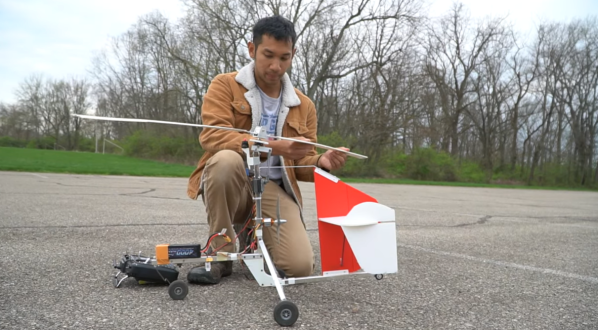
[Peter] recently got his hands on a full-scale autogyro. So it made sense to build a model to help learn to fly. This isn’t [Peter’s] first attempt with autogyro models. He’s built a few in the past, with limited success. This time he started from scratch and ran into even more problems!
Continue reading “Autogyro Models Are Hard — Even For [Peter Sripol]”