PCI Express (PCIe) has been around since 2003, and in that time it has managed to become the primary data interconnect for not only expansion cards, but also high-speed external devices. What also makes PCIe interesting is that it replaces the widespread use of parallel buses with serial links. Instead of having a bus with a common medium (traces) to which multiple devices connect, PCIe uses a root complex that directly connects to PCIe end points.
This is similar to how Ethernet originally used a bus configuration, with a common backbone (coax cable), but modern Ethernet (starting in the 90s) moved to a point-to-point configuration, assisted by switches to allow for dynamic switching between which points (devices) are connected. PCIe also offers the ability to add switches which allows more than one PCIe end point (a device or part of a device) to share a PCIe link (called a ‘lane’).
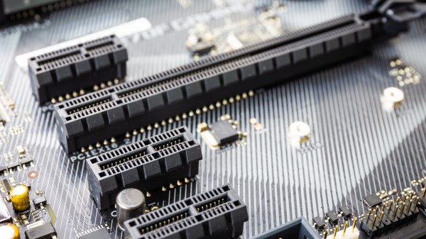
This change from a parallel bus to serial links simplifies the topology a lot compared to ISA or PCI where communication time had to be shared with other PCI devices on the bus and only half-duplex operation was possible. The ability to bundle multiple lanes to provide less or more bandwidth to specific ports or devices has meant that there was no need for a specialized graphics card slot, using e.g. an x16 PCIe slot with 16 lanes. It does however mean we’re using serial links that run at many GHz and must be implemented as differential pairs to protect signal integrity.
This all may seem a bit beyond the means of the average hobbyist, but there are still ways to have fun with PCIe hacking even if they do not involve breadboarding 7400-logic chips and debugging with a 100 MHz budget oscilloscope, like with ISA buses.
Continue reading “The Bus That’s Not A Bus: The Joys Of Hacking PCI Express”