We’ve often said that kids with hackers and makers for parents must be some of the luckiest kids in the world. While all the other children have to settle for some mass produced drivel from Toys“R”Us Amazon, they’ve got some of the most thoughtfully engineered and built toys and gadgets on the planet. After all, there’s no way any hacker worth their salt is going to give anything less than 110% for their own child.
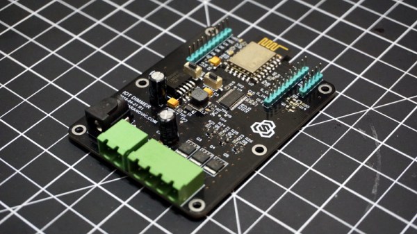
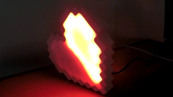
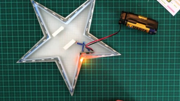
 A case in point is this RGB star nightlight that [Unexpected Maker] built for his children. The star itself is simple enough, just a basic shape printed in transparent PLA on his Prusa i3. The impressive part is how he lights it up. Rather than stick an Arduino or ESP8266 in there as we have seen plenty of times before, he’s put together his own custom ATTiny85 board specifically for controlling the RGB LED strips.
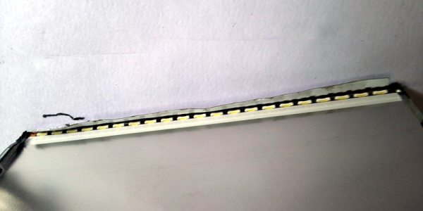
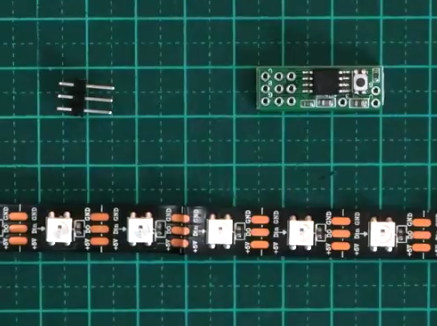
The board, which he calls TinyDev, is designed to be the same thickness as NeoPixel style LED strips so it can fit inside tight spaces. He solders it onto the tail end of his LED strip, adds a photoresistor so the star can tell when it’s time to light up, and then snakes the whole arrangement through a channel printed in the star itself. There’s a battery pack in the middle, but that’s about it. It really does allow for a remarkably clean LED strip implementation, and the mind can’t help but start thinking of interesting possibilities when you can tuck the controller into the same space as the lights themselves.
[Unexpected Maker] has made the TinyDev completely open source for anyone who wants to build their own, but it’s also available on Tindie if you want to get one to play with quickly. If you’re looking to light up the little one’s room with somewhat more mainstream methods, we’ve got that covered too.
Continue reading “Custom ATTiny85 Board Powers Kids’ Light Show”