If you’ve been making up for lost years of travel in 2023, you might have seen a fellow traveler in the airport terminal or train station walking with their luggage happily careening behind them. [Jesse R] and [Brian Lindahl] wanted more of that. They wanted an open-source, low-cost system that could be put in anything.
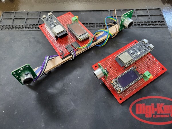
The basic principle is that they will have a transmitter that sends both a radio signal and an ultrasonic pulse. The receiver receives the radio signal and uses it as a reference for the two ultrasonic sensors. The time since the radio signal is compared between the two, and a distance and direction are established.
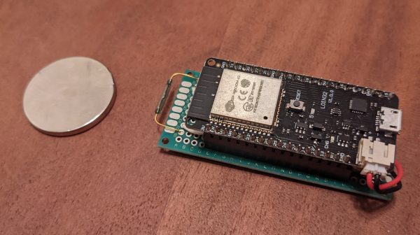
In practice, the radio is an ESP32-S3 using ESP-NOW (which we’ve seen relatively recently on another project), a protocol from Espressif that offers low latency 250 bytes payloads. The ultrasonic transceiver is based on Sparkfun’s HC-SR04. For prototyping purposes on the receiver, they just removed the transmitter to avoid populating the airwaves, as to listen, you had to transmit. The prototype was an electric wheelbarrow that would happily follow you around the yard wherever you go.
With the concept validated, they moved to a custom ultrasonic setup with a custom buffer amp and damp transistor, all centered around 20kHz. The simulations suggested they should have been better than the HC-SR04 from Sparkfun, but the 30-foot (9 meters) range went to 10 feet (3 meters). They ultimately returned to using Sparkfun’s circuit rather than the custom amp.
We’re looking forward to seeing the project continue. There are various challenges, such as variability in the speed of sound, echos and reflections, and ultrasonic line of sight. We love the peak behind the curtain that allows us to see what decisions get made and the data that informs those decisions. All the code and PCB design files are available on GitHub under an MIT and Creative Common license, respectively. This project was submitted as part of the 2o23 Hackaday Prize.
Video after the break.