At first glance, the Raspberry Pi Pico might seem like a bit of a black sheep when compared to the other offerings from the Raspberry Pi Foundation. While most of the rest of their lineup can run Linux environments with full desktops, the Pico is largely limited to microcontroller duties in exchange for much smaller price tags and footprints. But that doesn’t mean it can’t be coerced into doing some of the things we might want a mainline Pi to do, like run a web server.
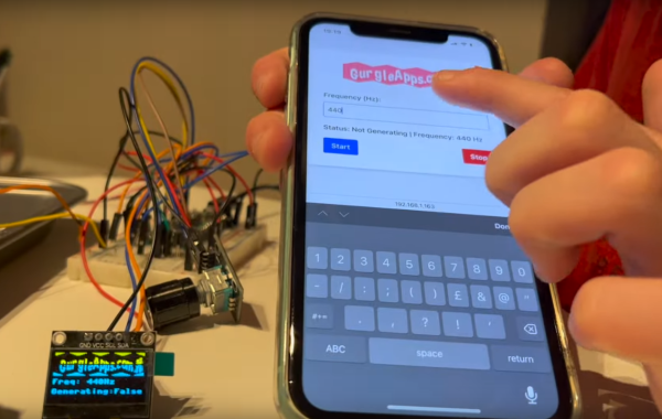
The project can run a static web page simply by providing the Pico with the project code available on the GitHub page and the HTML that you’d like the Pico to serve. It can be more than a static web page though, as it is also capable of running Python commands through the web interface as well. The server can pass commands from the web server and back as well, allowing for control of various projects though a browser interface. In theory this could be much simpler than building a physical user interface for a project instead by offloading all of this control onto the web server instead.
The project not only supports the RP2040-based Raspberry Pi Pico but can also be implemented on other WiFi-enabled microcontroller boards like the ESP8266 and ESP32. Having something like this on hand could greatly streamline smaller projects without having to reach for a more powerful (and more expensive) single-board computer like a Pi 3 or 4. We’ve seen some other builds on these boards capable of not only running HTML and CSS renderers, but supporting some image formats as well.
Continue reading “Pi Microcontroller Still Runs A Webserver”