Burning Propane Beautifully Illustrates How A Tesla Valve Works

When you hear the name “Tesla”, chances are good that thoughts turn instantly to the company that’s trying to reinvent the motor vehicle and every industry that makes it possible. While we applaud the effort, it’s a shame that they chose to appropriate the surname of a Serbian polymath as their corporate brand, because old [Nikola] did so many interesting things in his time, and deserves to be remembered in his own right.

Take the Tesla valve. In essence a diode for fluids, the Tesla valve uses a tortuous path to allow flow in one direction but severely restrict it in the other. Understanding how it works isn’t necessarily intuitive, though, which is why [NightHawkInLight] chose to demonstrate the Tesla valve principle with exploding propane. It’s not new territory to him; we’ve covered his propane-powered rifle in the past.

The swirling blue and green flame front in those experiments make burning propane the perfect working fluid to demonstrate how the Tesla valve works. The video below tells the tale, with high-speed footage showing the turbulence that restricts the reverse flow. The surprise discovery is that in the forward direction, the burning gas actually seems to accelerate as it moves down the valve; hypersonic Tesla plasma cannon, anyone?

We’ve seen Tesla valves before, including one made from a “Shrinky Dink”. That did a pretty good job of visualizing the flow patterns that make the valve work, but there’s a huge showmanship gap between tiny channels filled with colored water and the explosive decomposition of a fuel-air mix. It’s a bit riskier, and standard “don’t try this at home” disclaimers apply, but luckily [NightHawkInLight] still has his eyebrows, so he must be doing something right.

Continue reading “Burning Propane Beautifully Illustrates How A Tesla Valve Works”

3D-Printer And CNC Make This Russian Calculator Bilingual

Let’s be clear right up front: there are probably more obvious solutions to the problem of using a Russian calculator when you don’t speak Russian than printing new keys and engraving translated markings on them. But easy solutions are boring and generally considered beyond the scope of Hackaday articles, so let’s dive in.

They say that mathematics is the universal language, but that’s only true to an extent. Still, even with our limited non-existent Cyrillic skills, the Russian keyboard on this RPN calculator isn’t that hard to figure out. But as [Amen] points out, in the midst of fevered calculations, one prefers not to mentally translate Χ→П to STO or remember that В↑ is the Enter key. So he printed a set of replacements for the confusing keys from PLA. While pondering how to safely fixture such small parts for the later engraving step, [Amen] hit on a genius solution: move the print bed to the CNC router and fixture everything in one go. The resulting characters are large enough to be legible and deep enough to be filled with air-drying polymer clay for contrast. After sanding and polishing, the calculator looks like it came from the Министерство электронной промышленности that way.

Honestly, we’d love to get a look inside this calculator. The insides of Russian electronics can be fascinating, and we’ve even seen entire forums dedicated to decapping Russian parts. But we understand the desire to keep it intact.

Continue reading “3D-Printer And CNC Make This Russian Calculator Bilingual”

Are You Getting Your Money’s Worth From Threaded Inserts?

Have you ever wondered whether it’s worth the time and expense to install threaded inserts into your 3D-printed projects? [Stefan] from CNC Kitchen did, and decided to answer the question once and for all, with science.

If this sounds familiar, it’s with good reason: we covered [Stefan]’s last stab at assessing threaded inserts back in March. Then, he was primarily interested in determining if threaded inserts are better than threads cut or printed directly into parts. The current work is concerned with the relative value of different designs of threaded inserts. He looked at three different styles of press-in inserts, ranging in price from pennies apiece to a princely 25 cents. The complexity of the outside knurling seems not to be correlated with the price; the inserts with opposed helical knurls seem like they’d be harder to manufacture than the ones with simple barbs on the outside of the barrel, but cost less. And in fact, the mid-price insert outperformed the expensive one in pull-out tests. Surprisingly, the cheapest inserts were actually far worse at pull-out resistance than printing undersized holes and threading an M3 screw directly into the plastic.

[Stefan] also looked at torque resistance, and found no substantial difference between the three insert types. Indeed, none of the inserts proved to be the weak point, as the failure mode of all the torque tests was the M3 bolt itself. This didn’t hold with the bolt threaded directly into the plastic, of course; any insert is better than none for torque resistance.

We enjoyed seeing [Stefan]’s tests, and appreciate the data that can help us be informed consumers. [John] over at Project Farm does similar head-to-head tests, like this test of different epoxy adhesives.

Continue reading “Are You Getting Your Money’s Worth From Threaded Inserts?”

Tracking Wasted Time With A Ferrofluid Clock

We know this project is supposed to be about developing a fine-looking ferrofluid clock, and not about the value of procrastination. But after watching the video below, see if you don’t think that procrastination has taken these two students further than expected.

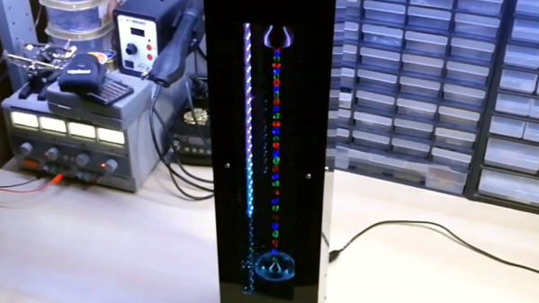
We first ran into [Simen] and [Amund] several months ago when they launched their ferrofluid project in a fit of “There’s got to be more to life than studying.” It seemed then that building a good-looking, functional ferrofluid display would be a temporary distraction, but the problems posed proved to be far deeper and thornier than either of the electrical engineering students expected. The idea is simple: contain a magnetic fluid between two transparent panels and create pixels using an array of electromagnets to move dots of the fluid around. The implementation, however, was another matter, with the ferrofluid itself proved to be the biggest obstacle. All the formulas they tried seemed to coagulate or degrade over time and tended to stain the glass. While the degradation was never fully sorted, they managed to work around the staining by careful cleaning of the glass and using a saturated brine solution to fill the container.

Backed by 252 electromagnets and drivers on ten custom PCBs, the video below shows the (mostly) finished panel in action as a clock. We’re impressed by the smoothness of the movements of each pixel, even if there’s a bit of drooping at the bottom thanks to gravity. As for the future of the project, that’s unclear since [Simen] is headed off for a NASA internship. We’re not sure if that was despite or because of this procrastination-driven project, but we congratulate him either way and look forward to hearing more from both of them in the future.

Continue reading “Tracking Wasted Time With A Ferrofluid Clock”

Conductive Tape Current Capacity Comparison

The world of DIY circuits for STEM and wearables has a few options for conductors. Wire with Dupont connectors is a standard, as is adhesive copper tape. There’s also conductive nylon/steel thread or ribbon. Which you choose depends on your application, of course, but as a general rule wire is cheap and ubiquitous while making connections is more challenging; copper tape is cheap and simple to use, but delicate and rips easily, so is best used for flat surfaces that won’t see a lot of stress or temporary applications; and conductive nylon thread or tape is better for weaving into fabrics.

The Brown Dog Gadgets team wanted to respond to a frequent question they are asked, what are the current limits for their Maker Tape (nylon/steel ribbon), so they ran some experiments to find out. In the name of Science you’ll see some flames in the video below, but only under extreme conditions.
Continue reading “Conductive Tape Current Capacity Comparison”

This FPV Tank Explores The Lawn

Radio control is good and all, and it’s always fun to watch a little vehicle scoot about the backyard. But there’s always something to be said for feeling as though you’re really in control. First person view, or FPV, is the way to do it, and [Brian] has gone down that route with this tidy tank build.

The tank is 3D printed, from the chassis right down to the wheels. There’s even a moving “eye” up front containing the FPV camera, controlled by a servo, allowing the driver to look up and down. A 5.8 GHz transmitter is used to send the signal back to the driver’s goggles. The tracks are a snap-together design that are fully 3D printed, requiring no additional metal links or hardware. Forward propulsion is courtesy of a pair of 12 volt gear motors, driven from an L298N motor driver. An Arduino Nano is used in conjunction with Spektrum RC gear to receive signals and tell the tank where to go.

It’s a tidy build that would be great fun to drive through the bushes or through the house. We’ve seen even tinier builds used to inspect crawlspaces. If you build one of your own, be sure to let us know.

How Safe Is That Ultrasonic Bath For Flux Removal?

How do you clean the residual flux off your boards? There are plenty of ways to go about the job, ranging from “why bother?” to the careful application of isopropyl alcohol to every joint with a cotton swab. It seems like more and more people are turning to ultrasonic cleaners to get the job done, though, and for good reason: just dunk your board and walk away while cavitation does the work for you.

But just how safe is it to sonically blast the flux off your boards? [SDG Electronics] wanted to know, so he ran some cleaning tests to get to the bottom of things. On the face of it, dunking a PCB in an aqueous cleaning solution seems ill-advised; after all, water and electricity famously don’t mix. But assuming all the nooks and crannies of a board can be dried out before power is applied, the cleaning solution itself should be of little concern. The main beef with ultrasonic cleaning seems to be with the acoustic energy coupling with mechanical systems on boards, such as crystal oscillators or micro-electrical-mechanical systems (MEMS) components, such as accelerometers or microphones. Such components could resonate with the ultrasonic waves and be blasted to bits internally.

To test this, [SDG Electronics] built a board with various potentially vulnerable components, including the popular 32.768-kHz crystal, cut for a frequency quite close to the cleaner’s fundamental. The video below goes into some detail on the before-and-after tests, but the short story is that nothing untoward happened to any of the test circuits. Granted, no components with openings as you might find on some MEMS microphones were tested, so be careful. After all, we know that ultrasound can deal damage, and if it can levitate tiny styrofoam balls, it might just do your circuit in.

Continue reading “How Safe Is That Ultrasonic Bath For Flux Removal?”