Science fiction predicted that we would one day all carry around tiny computers of great power. While smartphones are great, those predictions were more based on cuter systems that more closely approximated existing computers, with keyboards and screens. [Jean-Marc Harvengt] has built something along those very lines, and it’s called the T-COMPUTER.
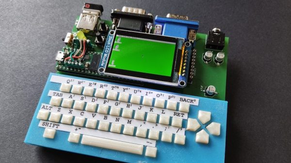
This build centers around the mighty Teensy 4.1. That means it’s got an 800 MHz Cortex-M7 processor, 1 MB of RAM, and 8 MB of flash – eclipsing the specs of many retrocomputers of yesteryear. [Jean-MarcHarvengt] has paired the Teensy with a 42-key keyboard and a TFT screen, making a compact handheld computer platform. It’s also got VGA out for display on a bigger screen, along with USB and an old-school Atari joystick port! Power is via a small rechargeable lithium cell on the back, and 16-bit stereo audio is available via a standard 3.5mm jack. There’s also a little GPIO available if you need to interface with something.
It’s capable of emulating the Commodore 64 and Super Nintendo, as well as more obscure systems like the Atari Lynx. And before you ask – yes, it can run DOOM. It’s a fun little platform that would be enjoyable for retrogaming and hacking on the go. If you want to build your own, files are readily available on Github to recreate the system.
Handheld computer builds are always growing in popularity now that so much computing power can be had in a tiny devboard formats. If you’ve built your own neat little rig, be sure to let us know! Video after the break.
Continue reading “Teensy Becomes Tiny Handheld Computer, Plays Emulators”