With the rise of big-name smartwatches in the marketplace, there are also a smattering of lower-end offerings. The M6 fitness band is one of them, and [Raphael] set about hacking the cheap device with a custom firmware of his own creation.
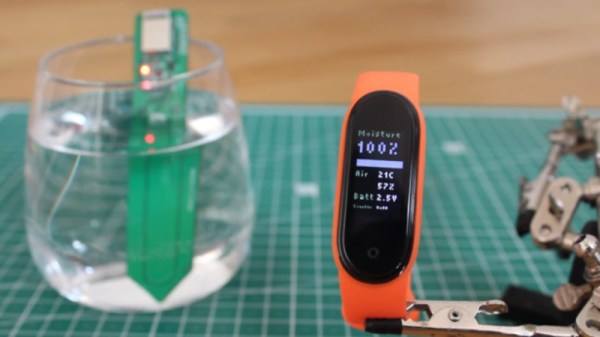
The M6 band, which sells for around $6, appears to trade on name similarity to the more expensive (~$50) Xiaomi Mi Smart Band 6 fitness tracker. Upon disassembly, [Raphael] found that the system-on-chip running the show is a Telink TLSR8232. It’s paired with a 160×80 display, a small LiPo battery for power, and a vibration motor and what appears to be a fake heart rate sensor.
[Raphael] wanted to flash the SOC with a new firmware, and learned a lot from code for a similar part created by [atc1441]. It took some time to figure out how to program the chip using the somewhat oddball SWire interface, but [Raphael] persevered and eventually got things going after much research and experimentation.
From there, it was yet further work to figure out how to read the capacitive button input as well as how to drive the screen, but [Raphael] succeeded in the end. The final result was whipping up a firmware that allowed him to read Bluetooth Low Energy soil moisture sensors he has installed in his plants at home.
It’s not [Raphael], aka [rbaron]’s first bite at the cherry; we’ve featured his efforts in hacking similar fitness bands before! Video after the break.
Continue reading “Reverse Engineering A Very Cheap Fitness Band”