We’d wager most readers aren’t intimately acquainted with wax motors. In fact, a good deal of you have probably never heard of them, let alone used one in a project. Which isn’t exactly surprising, as they’re very niche and rarely used outside of HVAC systems and some appliances. But they’re fascinating devices, and once you’ve seen how they work, you might just figure out an application for one.
[AvE] recently did a complete teardown on a typical wax motor, going as far as cutting the thing in half to show the inner workings. Now we’ve seen some readers commenting that everyone’s favorite foul-mouthed destroyer of consumer goods has lost his edge, that his newer videos are more about goofing off than anything. Well we can’t necessarily defend his signature linguistic repertoire, but we can confidently say this video does an excellent job of explaining these little-known gadgets.
The short version is that a wax motor, which is really a linear actuator, operates on the principle that wax expands when it melts. If a solid block of wax is placed in a cylinder, it can push on a piston during the phase change from solid to liquid. As the liquid wax resists compression, the wax motor has an exceptionally high output force for such a small device. The downside is, the stroke length is usually rather short: for the one [AvE] demonstrates, it’s on the order of 2 mm.
By turning heat directly into mechanical energy, wax motors are often used to open valves and vents when they’ve reached a specific temperature. The common automotive engine thermostat is a classic example of a wax motor, and they’re commonly found inside of dishwashers as a way to open the soap dispenser at the proper time during the cycle.
The production capability available to the individual hacker today is really quite incredible. Even a low-end laser engraver can etch your PCBs, and it doesn’t take a top of the line 3D printer to knock out a nice looking enclosure. With the wide availability of these (relatively) cheap machines, the home builder can churn out a very impressive one-off device on a fairly meager budget. Even low volume production isn’t entirely out of the question. But there’s still one element to a professional looking device that remains frustratingly difficult: a good looking front panel.
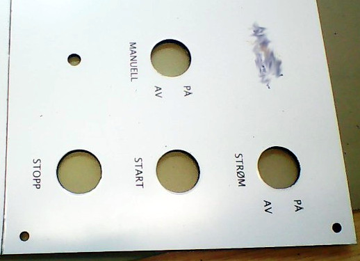
Now if your laser is strong enough to engrave (and ideally cut) aluminum sheets, then you’ve largely solved this problem. But for those of us who are plodding along with a cheap imported diode laser, getting text and images onto a piece of metal can be rather tricky. On Hackaday.io, [oaox] has demonstrated a cost effective way to create metal front panels for your devices using a print service that offers Dibond aluminum. Consisting of two thin layers of aluminum with a solid polyethylene core, this composite material was designed specifically for signage. Through various online services, you can have whatever you wish printed on a sheet of pre-cut Dibond without spending a lot of money.
As explained by [oaox], the first step is putting together the image you’ll send off to the printer using a software package like Inkscape. The key is to properly define the size of the Dibond plate in your software and work within those confines, otherwise the layout might not look how you expected once the finish piece gets back to you. It’s also important to avoid lossy compression formats like JPEG when sending the file out for production, as it can turn text into a mushy mess.
When you get the sheet back, all you need to do is put your holes in it. Thanks to the plastic core, Dibond is fairly easy to cut and drill as long as you take your time. [oaox] used a step drill for the holes, and a small coping saw for the larger openings. The final result looks great, and required very little effort in the grand scheme of things.
But how much does it cost? Looking around online, we were quoted prices as low as $7 USD to do a full-color 4×4 inch Dibond panel, and one site offered a 12×12 panel for $20. For a small production run, you could fit several copies of the graphics onto one larger panel and cut them out with a bandsaw; that could drop the per-unit price to only a couple bucks.
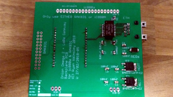
[Ryan Wamsley] has spent a lot of time over the past few months working on a new project, the Ultimate LoRa backplane. This is as its name suggests designed for LoRa wireless gateways, and packs in all the features he’d like to see in a LoRa expansion for the Nano Pi Duo.
His design features a three-terminal regulator, and in the quest for a bit more power efficiency he did what no doubt many of you will have done, and gave one of those little switching regulator modules in a three-terminal footprint a go. As part of his testing he inadvertently touched the regulator, and was instantly rewarded with a puff of smoke from his Nano Pi Duo. As it turned out, the regulator was susceptible to electrical noise, and had a fault condition in which its input voltage was routed directly to its output. As a result, a component in the single board computer received way more than its fair share, and burned out.
If there is a moral to be extracted from this story, it is to never fully trust a cheap drop-in module to behave exactly as its manufacturer claims. [Ryan]’s LoRa board lives to fight another day, but the smoke could so easily have come from more components.
So that’s the Fail of The Week part of this write-up complete, but it would be incomplete without the corresponding massive win that is [Ryan]’s LoRa board itself. Make sure to take a look at it, it’s a design into which a lot of attention to detail has been put.
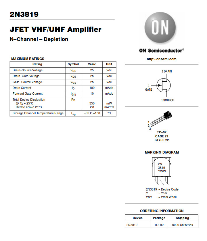
The 2N3819 is the archetypal general-purpose N-channel FET. (ON Semiconductor)
Over the recent weeks here at Hackaday, we’ve been taking a look at the humble transistor. In a series whose impetus came from a friend musing upon his students arriving with highly developed knowledge of microcontrollers but little of basic electronic circuitry, we’ve examined the bipolar transistor in all its configurations. It would however be improper to round off the series without also admitting that bipolar transistors are only part of the story. There is another family of transistors which have analogous circuit configurations to their bipolar cousins but work in a completely different way: the Field Effect Transistors, or FETs.
In a way it’s less pertinent to look at FETs in the way we did bipolar transistors, because while they are very interesting devices that power much of what you will do with electronics, you will encounter them as discrete components surprisingly rarely. Every CMOS device you deal with relies on FETs for its operation and every high-quality op-amp you throw a signal at will do so through a FET input, but these FETs are buried inside the chip and you’d be hard-pressed to know they were there if we hadn’t told you. You’d use a FET if you needed a high-impedance audio preamp or a low-noise RF amplifier, and FETs are a good choice for high-current switching applications, but sadly you will probably never have a pile of general-purpose FETs in the way you will their bipolar equivalents.
That said, the FET is a fascinating device. Join us as we take an in-depth look at their operation, and how and where you might use one.
FET basics
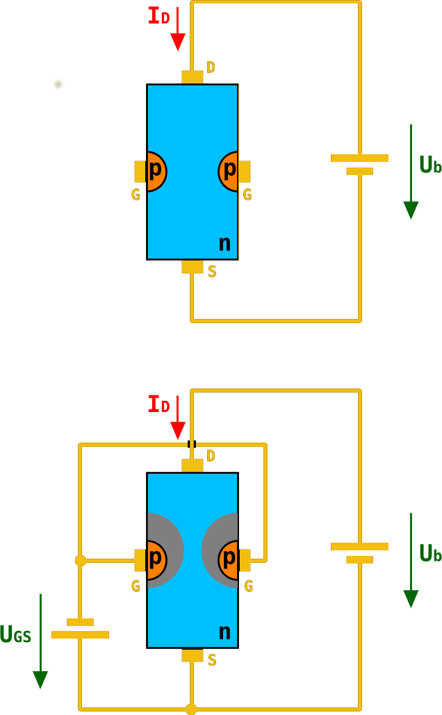
A diagram of an n-channel JFET. As the negative gate voltage on the p-type silicon decreases in the lower diagram, its electric field restricts the area through which electrons can flow in the n-type channel. Chtaube,(CC BY-SA 2.0 DE)
A basic FET has three terminals, a source (the source of electrons), a gate (the control terminal), and a drain (where electrons leave the device). These are analogous to the terminals on a bipolar transistor, in that the source fulfills a similar role to the emitter, the gate to the base, and the drain to the collector. Thus the three basic bipolar transistor circuit configurations have equivalents with a FET; common-emitter becomes common-source, common-base becomes common-gate, and an emitter follower becomes a source follower. It is dangerous to stretch the analogy between bipolar transistors and FETs too far, though, because of their different mode of operation. A closer similarity exists between a FET and a triode tube, if that helps.
The simplest FET for demonstration purposes has a piece of N-type semiconductor with source and drain connections at opposite ends, and a zone of P-type semiconductor deposited in its middle. This is referred to as an N-channel junction FET or JFET, because the channel through which current flows is N-type semiconductor, and because a diode junction exists between gate and channel. There are equivalent P-channel devices, just as there are PNP and NPN bipolar transistors.
Were you to bias an n-channel JFET as you would a bipolar transistor with a positive bias on its gate, the diode between gate and source would conduct, and the transistor would remain a diode with two cathode terminals. If however you give the gate a negative bias compared to the source, the diode becomes reverse-biased, and no current to speak of flows in the gate.
A characteristic of a reverse-biased diode is that it has a depletion zone between anode and cathode, an area in which there are no electrons. This is what causes the diode to no longer conduct, and the size of the depletion zone depends upon the size of the electric field that exists across it. If you’ve ever used a varicap diode, the capacitance between the two sides of this variable-width zone is the property you are exploiting.
In a FET, the depletion zone stretches from the gate region into the channel, and since its size can be adjusted by the gate voltage it can be used to “pinch” the remaining conductive region within the channel. Thus the area through which electrons can flow is controlled by the gate voltage, and thus the current that flows between drain and source is proportional to the gate voltage. We have an amplifier.
A simple FET radio receiver circuit showing FET biasing. The gate is biased at ground potential through the inductor, and the source is held above ground by the current in the 5K resistor. Herbertweidner [Public domain].In the JFET diagram above, the negative gate bias is represented by a battery. Tube enthusiasts may have encountered equipment that derives negative grid bias from a power supply, and you will find tube power units that include a -150 V rail for this purpose. In general though this is inconvenient in a FET circuit even though the voltage is lower, because of the extra cost of a negative regulator.. Instead the gate is held at a lower potential than the source by careful selection of a source resistor such that the current flowing through it brings the source up above ground, and a gate bias circuit that holds the gate close to ground. The base resistor chain from the bipolar circuit is for this reason often replaced with either a single resistor to ground, or a gate circuit with a very low DC resistance to ground such as an inductor.
MOSFETs, where the FET becomes more useful
Internal structure of an N-channel MOSFET. Fred the Oyster [Public domain].The JFET we have described is the simplest of field-effect devices, but it is not the one you will encounter most frequently. MOSFETs, short for Metal Oxide Semiconductor FETs, have a similar source, gate, and drain, but instead of relying on a depletion zone in a reverse-biased diode, they have a thin layer of insulation. The electric field from the gate acts across this insulation and pinches the conductive region in the channel through repulsion of electrons, with the same effect as it has in the JFET. It is beyond the scope of this piece to go into their mechanisms, but you will encounter two types of MOSFET: depletion mode devices that require the same negative bias as the JFET, and enhancement mode MOSFETS that require a positive bias.
Why would you use a FET?
So we’ve described the FET, and noted that while its mode of operation is different to that of a bipolar transistor it does a substantially similar job. Why would we use a FET then, what advantages does it offer us? The answer comes from the gate being insulated either by a depletion region in a JFET or by an insulating layer in a MOSFET. A FET is a voltage amplifier rather than a current amplifier, its input impedance is many orders higher than that of a bipolar transistor, and thus you will find FETs used in many applications that require a high impedance small-signal amplifier. The input of a high-performance op-amp will almost certainly be a FET, for example.
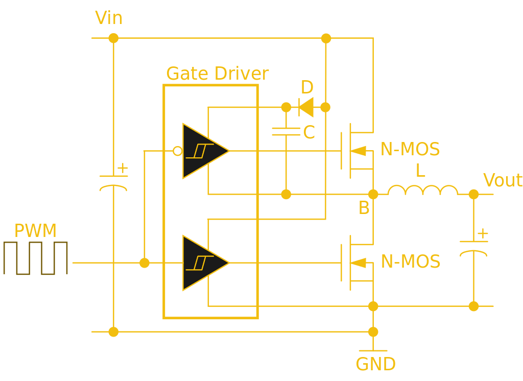
This half-bridge power MOSFET driver circuit uses a specialist gate driver IC with a pair of Schmidt buffers to deliver the initial surge required for a fast-turn-on time. Wdwd (CC BY 3.0).
The high input impedance has another effect less coupled to small signal work. Where a bipolar transistor requires significant base current to turn itself on, the corresponding FET requires almost none. Thus almost all complex integrated circuit logic devices are FET-based rather than bipolar because of the huge power saving that can be made by not needing to supply the base current demands of many thousands of bipolar transistors.
The same effect influences the choice of FETs for power switching, while a bipolar transistor’s base current is proportional to its collector current and thus it will need a significant driver, by contrast a power MOSFET requires virtually no standing gate current after an initial surge. A MOSFET power switch can thus be built requiring much less in the way of drive electronics and much more efficiently than a corresponding bipolar switch, and makes possible some of the tiny driver boards you might be used to for driving motors in your 3D printer, or your multirotor.
Through the course of this series you should have acquired a solid grounding in basic bipolar transistor principles, and now you should be able to add FETs to that knowledge base. We suggested you buy a bag of 2N3904s to experiment with in one of the previous articles, can we now suggest you do the same with a bag of 2N3819s?
Have you ever torn open an Ethernet jack? We’d bet the vast majority of readers — even the ones elbow-deep into the hardware world — will answer no. So we applaud the effort in this one, but the conclusion landed way off the mark.
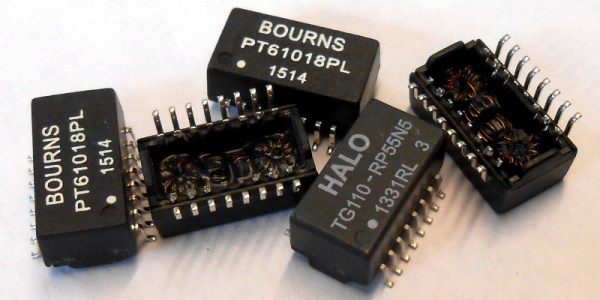
In the last few days, a Tweet showing a Raspberry Pi with its Ethernet socket broken open suggested the little PCB inside it is a hidden bug. With more going on inside than one might expect, the conclusion of the person doing the teardown was that the Raspberry Pi foundation are spying upon us through our Ethernet traffic. That’s just not the case. But we’re still excited about what was found.
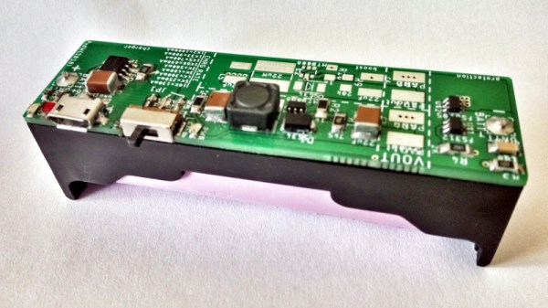
We’re all used to battery booster packs containing a Li-ion or Li-poly cell and a little inverter circuit, they are a standard part of 21st century daily survival for those moments when smartphone battery lives don’t perform as advertised. But how many of us have considered what goes into them, and further how many of us have sought to produce the best one possible rather than a unit built at the lowest price?
You might think that there was nothing new that could be learned about a Li-ion battery booster, but it’s always worth a look at a well-executed piece of work. We noticed he refers to Li-poly cells while using what appears to be a Li-ion 18650 cell. Most likely this is merely an oversight.
There is a lot to know about the characteristics and safety of the lithium-chemistry rechargeables, you may find [Sean Boyce]’s article on the subject to be an interesting read.
If you are a regular searcher for exotic parts among the virtual pages of semiconductor supplies catalogs, you will have probably noticed that for a given function it is most often the part bearing the Analog Devices logo that is the most interesting. It may have more functionality, perhaps it will be of a higher specification, and it will certainly have a much higher price. [Zeptobars] has decapped and analyzed an AD chip that holds all three of those honors, the AD9361 SDR transceiver.
It’s placed under a slightly inflammatory title, “when microchips are more profitable than drugs“, but does make a good job of answering why a semiconductor device at the very cutting edge of what is possible at the time of release can be so expensive. The AD9361 is an all-in-one SDR transceiver with an astonishing bandwidth, and as such was a particularly special device when it reached the market in 2013. We see some particularly fine examples of on-chip inductors and PLL circuitry that must have consumed a significant design effort to preserve both bandwidth and noise characteristics. This is an item of physical beauty at a microscopic scale as well as one of technical achievement.
The financial analysis puts Analog Devices’s gross profit at about $103 of the $275 retail purchase price of an AD9361. The biggest slice at $105 goes to the distributor, and surprisingly the R&D and manufacturing costs are not as large as you might expect. How accurate these figures are is anybody’s guess, but they are derived from an R&D figure in the published financial report, so there is some credence to be given to them.
We’ve featured [Zeptobar’s] work before more than once. A look at fake Nordic Semi parts for example or a Soviet i8080 clone have received their treatment. Always a source to watch out for!

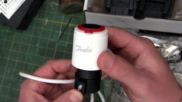
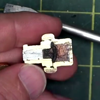 [AvE] recently did a complete teardown on a typical wax motor, going as far as cutting the thing in half to show the inner workings. Now we’ve seen some readers commenting that everyone’s favorite foul-mouthed destroyer of consumer goods has lost his edge, that his newer videos are more about goofing off than anything. Well we can’t necessarily defend his signature linguistic repertoire, but we can confidently say this video does an excellent job of explaining these little-known gadgets.

![A simple FET radio receiver circuit showing FET biasing. The gate is biased at ground potential through the inductor, and the source is held above ground by the current in the 5K resistor. Herbertweidner [Public domain].](https://hackaday.com/wp-content/uploads/2018/06/1kreiser_mit_fet.png)
![Internal structure of an N-channel MOSFET. Fred the Oyster [Public domain].](https://hackaday.com/wp-content/uploads/2018/04/n-channel_mosfet-svg1.png)

 The financial analysis puts Analog Devices’s gross profit at about $103 of the $275 retail purchase price of an AD9361. The biggest slice at $105 goes to the distributor, and surprisingly the R&D and manufacturing costs are not as large as you might expect. How accurate these figures are is anybody’s guess, but they are derived from an R&D figure in the published financial report, so there is some credence to be given to them.