The amateur astronomy world got a tremendous boost during the 1960s when John Dobson invented what is now called the Dobsonian telescope. Made from commonly-sourced materials and mechanically much simpler than what was otherwise available at the time, the telescope dramatically reduced the barrier to entry for larger telescopes and also made them much more portable and inexpensive.
For all their perks, though, a major downside is increased complexity when building automatic tracking systems. [brickbots] went a different way when solving this problem, though: a plate solver.
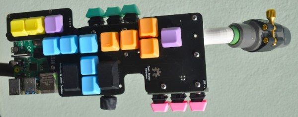
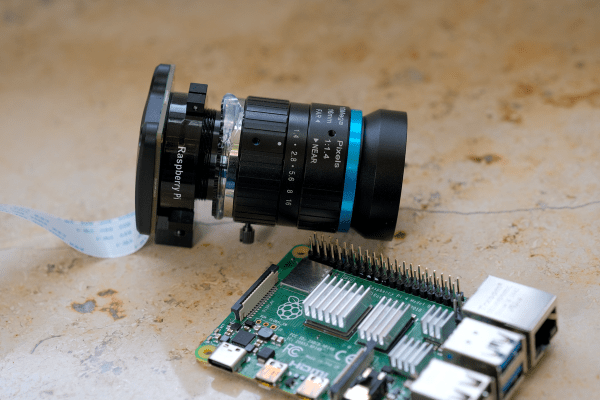
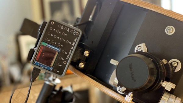
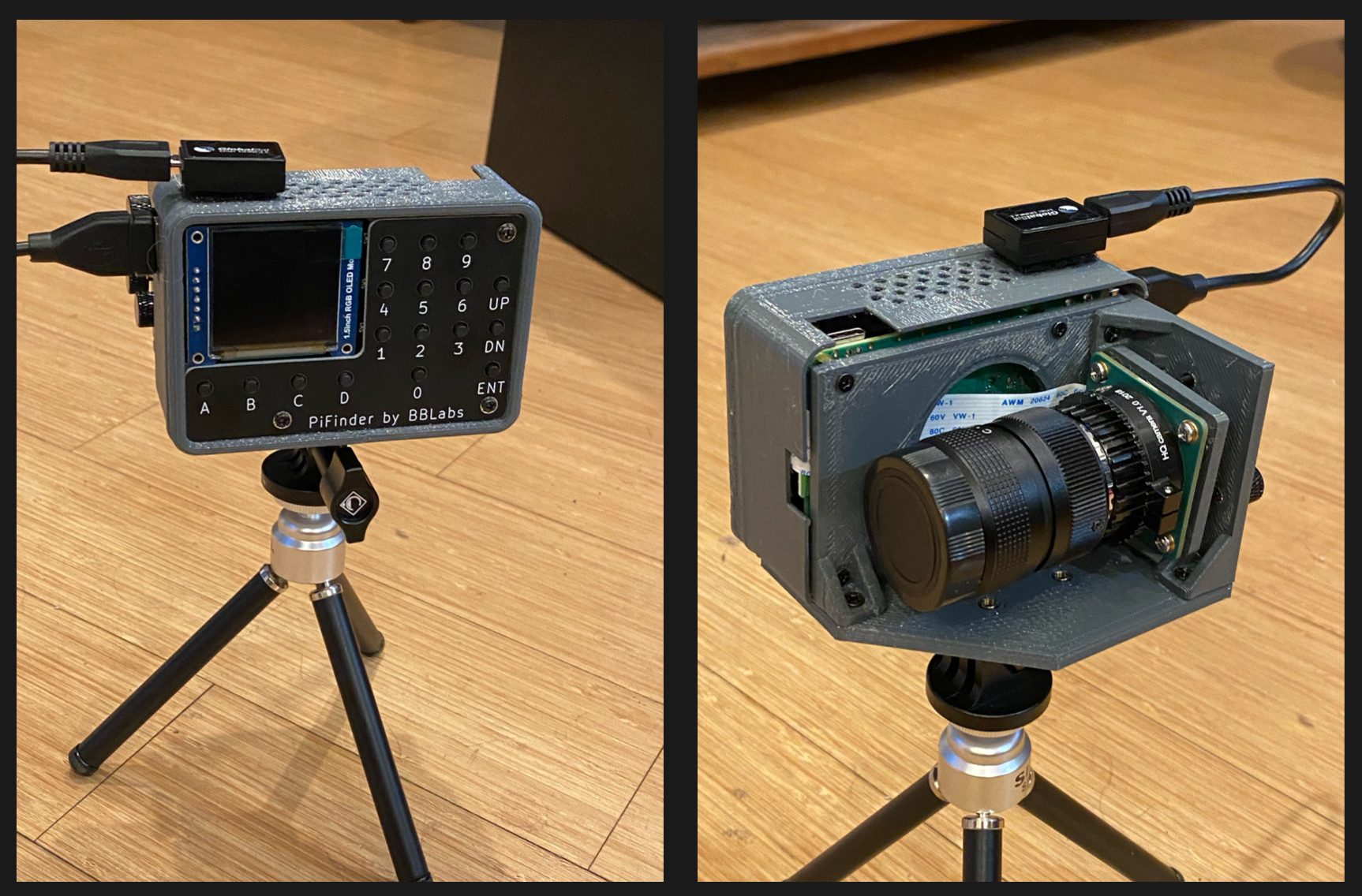 Plate solving is a method by which the telescope’s field of view is compared to known star charts to determine what it’s currently looking at. Using a Raspberry Pi at the center of the build, the camera module pointed at the sky lets the small computer know exactly what it’s looking at, and the GPS system adds precise location data as well for a quick plate solving solution. A red-tinted screen finishes out the build and lets [brickbots] know exactly what the telescope is pointed towards at all times.
While this doesn’t fully automate or control the telescope like a tracking system would do, it’s much simpler to build a plate solver in this situation. That doesn’t mean it’s impossible to star hop with a telescope like this, though; alt-azimuth mounted telescopes like Dobsonians just need some extra equipment to get this job done. Here’s an example which controls a similar alt-azimuth telescope using an ESP32 and a few rotary encoders.