WS2812s On A 6502

We can still remember when the WS2812 LED first came into our consciousness, way back in the mists of time. The timing diagrams in the datasheet-of-questionable-veracity made it sound quite tricky, with tight timing tolerances and essentially a high-speed two-bit PWM data protocol at 500 kHz. It was a challenge to bit-bang with an ATtiny85 back then, but there’s no way something as old and crusty as an Apple II would be up to snuff, right?

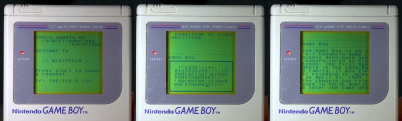
[Anders Nielsen] took up the challenge of getting the venerable 6502 processor to drive Neopixels and won! After all, if the chip is good enough for Bender and the Terminator T-800, it should be able to blink some colored LEDs, right? The secret sauce is shift registers!

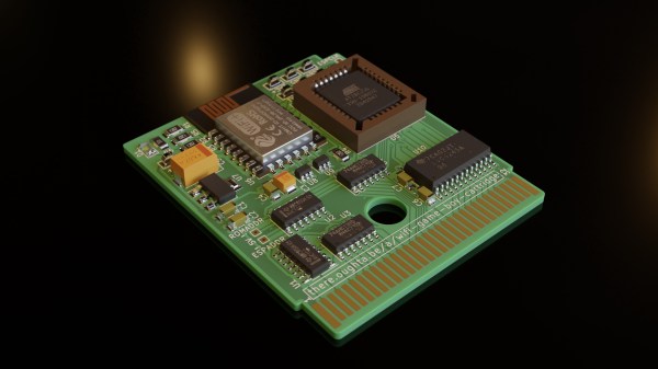
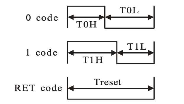
Specifically, [Anders] abuses the 74LS165 parallel-in, serial-out shift register for his dirty work. Instead of bit-banging the WS2812’s “long high is a 1, short high is a 0” signal directly, the first few bits of the shift register are hard-wired to VCC and the last few to GND.

The bits in the middle determine if the pulse shifted out is long or short, and they’re set by the 6502, through a 6522 VIA chip, just like the Apple II would have. Clocking the data out of the shift register handles the timing-critical stuff. Very clever!

Video below the break.

Continue reading “WS2812s On A 6502”

Building MS-DOS From Scratch Like It’s 1983

Building a complete operating system by compiling its source code is not something for the faint-hearted; a modern Linux or BSD distribution contains thousands of packages with millions of lines of code, all of which need to be processed in the right order and the result stored in the proper place. For all but the most hardcore Gentoo devotees, it’s way easier to get pre-compiled binaries, but obviously someone must have run the entire compilation process at some point.

What’s true for modern OSes also holds for ancient software such as MS-DOS. When Microsoft released the source code for several DOS versions a couple of years ago, many people pored over the code to look for weird comments and undocumented features, but few actually tried to compile the whole package. But [Michal Necasek] over at the OS/2 Museum didn’t shy away from that challenge, and documented the entirely-not-straightforward process of compiling DOS 2.11 from source.

The first problem was figuring out which version had been made available: although the Computer History Museum labelled the package simply as “MS-DOS 2.0”, it actually contained a mix of OEM binaries from version 2.0, source code from version 2.11 and some other stuff left from the development process. The OEM binaries are mostly finished executables, but also contain basic source code for some system components, allowing computer manufacturers to tailor those components to their specific hardware platform.

Compiling the source code was not trivial either. [Michal] was determined to use period-correct tools and examined the behaviour of about a dozen versions of MASM, the assembler likely to have been used by Microsoft in the early 1980s. As it turned out, version 1.25 from 1983 produced code that most closely matched the object code found in existing binaries, and even then some pieces of source code required slight modifications to build correctly. [Michal]’s blog post also goes into extensive detail on the subtle differences between Microsoft-style and IBM-style DOS, which go deeper than just the names of system files (MSDOS.SYS versus IBMDOS.COM).

The end result of this exercise is a modified DOS 2.11 source package that actually compiles to a working set of binaries, unlike the original. And although this does not generate any new code, since binaries of DOS 2.11 have long been available, it does provide a fascinating look into software development practices in an age when even the basic components of the PC platform were not fully standardized. And don’t forget that even today some people still like to develop new DOS software.

A briefcase sized electronic machine with many indicator lamps and switches

Restoring A Vintage IBM I/O Tester

By now, [CuriousMarc] and his team of volunteers are well versed in 1960s hardware restoration. So when a vintage IBM I/O Tester came into their possession, a full machine makeover was all but inevitable.

The I/O Tester dates from around 1965, which roughly coincides with the introduction of IBM’s lauded System/360 computer mainframe. In addition to the computer itself, business customers could order a variety of peripherals with their computing system. These included storage devices, printers, additional operator consoles, and so on. Since these peripherals shared the same I/O design, a portable hardware testing rig was a sensible design choice. One portable low-voltage tester could be paired with any number of IBM peripherals, doing away with the need to have unique debugging panels on every piece of computing hardware.

Fast forward to the present day, and the IBM I/O Tester looks positively antique with its blinkenlight lamp panel and switches. To use the tester, simply connect up one (or both) of its chunky 104-pin connectors to your IBM peripheral of choice, insert the accompanying paper overlay, and voilà. Operators could then observe the status of the many lamps to evaluate the inner digital workings of the connected peripheral. Depending on the connected hardware, the tester could reveal the contents of data registers, printing status, disk and tape transfer status, and probably much more. The purpose of the tester’s ninety indicator lights is completely dependent on the attached peripheral, and the paired paper overlays are essential to comprehend their meaning.

After [Ken Shirriff] deciphered the documentation, it wasn’t long before the tester could be powered up using 24 VAC (normally supplied by the equipment being tested). Several burned out lamps were noted for replacement. The lamp assemblies required minor surgery due to a dubious design choice, and at least one of the toggle switches needed a new guide and a heavy dose of contact cleaner before it came back to life.

For the moment, [CuriousMarc] is using the blinkenlights panel as a surprisingly striking retro clock. With a literal truckload of vintage IBM hardware sitting in his storage, it’ll be exciting to see whether this restored tester will be pulled back into operational service someday. Readers should also check out our coverage of his previous major project, restoring an Apollo Guidance Computer.

Continue reading “Restoring A Vintage IBM I/O Tester”

ESP8266 Based WiFi Game Boy Cartridge Browses WikiPedia

[Sebastian Staacks] came across his old Game Boy and was wondering (as you do) what happened to recent attempts at getting a WiFi interface wedged into a standard cartridge. After a while the conclusion was that people had been scuppered by approaching the problem in a way that made it too hard. Obviously that meant it was necessary to follow through and build something, which is precisely what he did with his WiFi Game Boy Cartridge.

A trend lately has been to hook up a fast microcontroller to a bus, then move the whole interfacing shenanigans into software. This works fine in some circumstances, but for the GB interface, it’s not so easy. The GB is powered by the Sharp LR35902, running at a smidge over 4 MHz, but its machine cycle takes four clocks giving an instruction rate of only 1 MHz. The cartridge interface presents the raw CPU bus directly. This is both good and bad. It’s good, because it enables all kinds of expansion modules, like cameras, printers, and other custom peripherals, but it’s bad because the burden of interfacing with the CPU, at its full speed, lies squarely in the cartridge’s remit.

Rather than trying to hook this bus directly to a fast microcontroller, [Staacks] has taken a different approach; by decoding the address bus with discrete logic, it was easy to derive chip selects for an embedded ESP8266 as well as a socketed EEPROM. The clock for the former was also gated and sent into the ESP8266, generating an interrupt to wake it up. The EEPROM stores a simple application whose job is to present an OSD keyboard and send requests to Wikipedia, via the ESP8266 WiFi stack. The resulting text is then displayed on the 160×144 dot matrix display. The interrupt latency of the ESP8266 was mitigated by the application simply discarding the first data byte sent to it, and retrying the access. This way the ESP8266 could spend the majority of its time dealing with wireless duties, only pausing to swap a byte now-and-then with the application. A simple solution which appears to actually work! If you’re up for building one of these and writing your own applications, you can wander over to GitHub, clone yourself a copy and crack on!

We’ve seen a few attempts at doing this before, [davedarko] tried with this project, and if you search hackaday.io you’ll get loads of GB hacks to browse. Finally a recent twitter thread also points to another effort to do something similar with Wi-Fi, but development is still ongoing. We’ll check back later!

Continue reading “ESP8266 Based WiFi Game Boy Cartridge Browses WikiPedia”

A Well Documented BreadBoard Computer Shows Dedication

These pages have not been exactly devoid of home-built computers, with those constructed on solderless breadboard less frequent, but still not rarities. But what is more of a rarity is this ground-up 8-bit 74xx logic-based computer (video, embedded below) with full source, an emulator, assembler and test suite. [JDH] spent a solid couple of weeks working late into the night to build this, and the results show for themselves.

The new JDH-8 is now a figment of reality.

The architecture is a traditional 8-bit load/store microcoded processor with the microcode stored in easily programmable AT28C64 EEPROMs for ease of tweaking.  The address bus is 16-bits, which is quite ample for this, and puts it in line with (admittedly more sophisticated) 8-bit micros of old such as the 6502. There is also a hardware stack, and a discrete-logic ALU as well! Finally, since that wasn’t enough work already, he added in his own discrete logic video controller.

Wise people simulate before prototyping something like this

There are sixteen instructions covering memory access, ALU operations and I/O operations. One of the great things about this project is that [JDH] readily admits the mistakes made along the way, and how the architecture didn’t need to be this complex. One example is that hardware stack wasn’t really necessary as it could just have been implemented in software. Also, due to the implementation, memory accesses were so fast compared with the achievable cycle time, that there really was no point to using load/store architecture at all! Still, [JDH] had fun building and programming it!

It was interesting to see the use of LogiSim-Evolution to debug first a high level model of the architecture and then the translation into TTL chips. This scribe wasn’t aware of that tool (the shame!) but is going to try this out real soon.

All code for the software side of things can be found on the project GitHub. Perhaps the hardware design will appear there as well, be at the time of writing we couldn’t seem to find it.

Can’t get enough breadboard computers? (We can’t) check this out from last year. Stuck for a suitable enclosure for your latest bread breadboard computer? How about a bread bin.

Continue reading “A Well Documented BreadBoard Computer Shows Dedication”

A Slim 7400 Logic VGA Board For All Your Retro Needs

Over the years we’ve seen a number of hackers generate VGA with 74xx logic chips, but they’ve generally not been the most practical of builds. Often put together as part of a competition or purely for the challenge, these circuits are usually implemented in a mass of jumper wires and often take up multiple breadboards. Not exactly something you can toss in a drawer when you’re done with it.

But the Vectron VGA Plus, created by prolific hacker [Nick Bild], manages to improve on things considerably. Designed specifically to be smaller and simpler than its predecessors, the custom PCB contains far fewer chips than we’re used to seeing for this kind of thing. At the same time it provides a handy header row along the bottom that allows the user to connect whatever they’re working on, from microcontrollers to retro computers.

When your breadboard looks like this, it’s time for a PCB.

It looks like the PCB could still be shrunk down considerably if you’re really looking to maximize desk space, but we imagine for his purposes, [Nick] felt this was more than compact enough. Especially when you look at what the same circuit looked like during the breadboard phase. Yikes.

So, what did it take to simplify this 640 x 480 VGA interface? The short answer is adding more RAM. Wherever possible, dedicated hardware was replaced with software operations that could be performed by the externally connected device. [Nick] has provided some sample code for the Arduino that lets the microcontroller push data into the board’s memory and take control.

We can trace the origins of this project back a few years, to when [Nick] was working on adding an LCD to his homebrew 6502 computer. A few months later he put together the earlier version of this board, the Vectron VGA, before switching gears and handing VGA generation duty over to a FPGA. We’re excited to see the next evolution of this project, and given the track record of this particular hacker, we shouldn’t have to wait long before it hits our inbox.

MAC TIP Diagnoses Your Old Zip And Jaz Drives

Trouble In Paradise (TIP) was a popular Windows-only tool for troubleshooting  Iomega Jaz and Zip drives way back when. The drives have fallen out of favor with PC, but the drives are still highly prized amongst classic Mac collectors, who use the SCSI versions as boot disks for the vintage machines. Thus, [Marcio Luis Teixeira] set about porting the TIP tool to the platform.

Macintosh utilities used to have so much personality about them.

It all came about because running the original TIP recovery tool became difficult in the modern era. One must dig up a old Windows 98 machine and SCSI adapters in order to use it with Macintosh-compatible Zip or Jaz drives. This inspired [Marcio] to reach out to the developer, [Steve Gibson], who provided the original x86 assembly code for the tool.

[Marcio] then ported this line-by-line into C and compiled it with a retro Macintosh compiler to get TIP up and running on the classic Mac platform. Now, it’s possible to check and test Zip and Jaz drives and media on your old Mac without having to mess around with a vintage Windows machine.

It took plenty of effort, and the generous donation of code from [Steve Gibson], and all involved should be applauded for their work. It’s not every day we see such an impressive port, but they come along every now and then.

Meanwhile, if you’ve been tinkering on your own projects with Iomega’s classic removable storage, don’t hesitate to let us know! Video after the break.

Continue reading “MAC TIP Diagnoses Your Old Zip And Jaz Drives”