There’s hardly any piece of test equipment more fundamental than a volt ohm meter. Today you’re likely to have a digital one, but for most of history, these devices had real needle meters. The AVOmeter Model 8 Mark III that [Jeff Tranter] shows off had an odd banana-shaped meter. Maybe that goes with the banana plugs. You can get a closer view of this vintage piece of equipment in the video after the break.
Even the outside description of the meter is interesting. There were several unique features. For example, if the meter goes full scale a little button pops out and disconnects the probes to protect the meter. Another unusual control reversed the polarity of the leads so you didn’t have to swap them manually.
Some of the other features will be familiar to anyone who has used a good analog meter. For example, the meter movement has a mirror under the needle. This is used to make sure you are looking straight down on the needle when making readings. If you can see the reflection of the needle, then you are off to one side and will not read the precise value you are interested in.
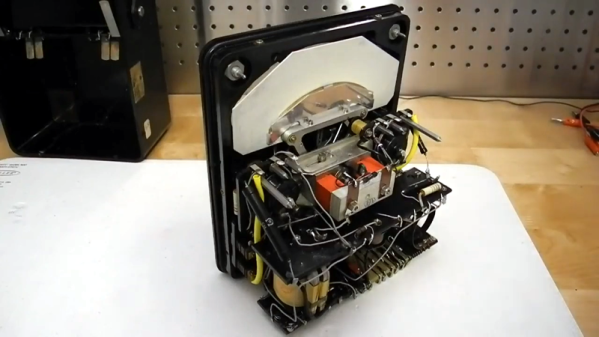
If you only want to see the insides, [Jeff] teases you until around the six minute mark. There are no active devices and this meter is old enough to not use a printed circuit board. The AC ranges work with a transformer and germanium diodes. The rest of the circuit is mostly a bunch of resistors.
The point to point wiring always makes us wonder who built this thing sixty years ago. You can only wonder what they would think if they knew we were looking at their handiwork in the year 2020.
We see a lot of meter clocks, but it would be a shame to tear this unique meter apart for its movement. Perhaps someone should make a clock that outputs a voltage to a terminal so you could read it with your favorite meter. This instrument was probably pretty precise for its day, but we doubt it can match a modern 6.5 digit digital instrument.
Continue reading “Amp Volt Ohm Meter Model 8 Mark III From The 1960s”