With CNC machines, getting the best results depends on knowing how fast your tool is moving relative to the workpiece. But entry-level CNC routers don’t often include a spindle tachometer, forcing the operator to basically guess at the speed. This DIY optical spindle tach aims to fix that, and has a few nice construction tips to boot.
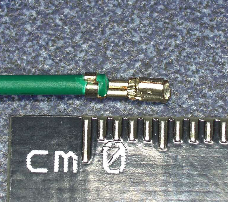
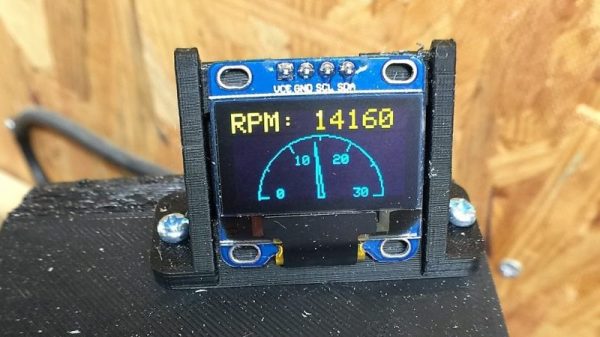
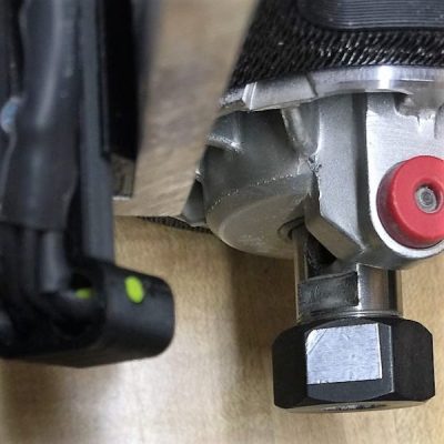 The CNC router in question is the popular Sienci, and the 3D-printed brackets for the photodiode and LED are somewhat specific for that machine. But [tmbarbour] has included STL files in his exhaustively detailed write-up, so modifying them to fit another machine should be easy. The sensor hangs down just far enough to watch a reflector on one of the flats of the collet nut; we’d worry about the reflector surviving tool changes, but it’s just a piece of shiny tape that’s easily replaced. The sensor feeds into a DIO pin on a Nano, and a small OLED display shows a digital readout along with an analog gauge. The display update speed is decent — not too laggy. Impressive build overall, and we like the idea of using a piece of PLA filament as a rivet to hold the diodes into the sensor arm.
Want to measure machine speed but don’t have a 3D printer? No worries — a 2D-printed color-shifting tach can work too.
Continue reading “Optical Tach Addresses The Need For Spindle Speed Control”