See Aerodynamics In Action With A Desktop Wind Tunnel

While most of us don’t design aircraft or racing cars, it’s likely that we’re still fascinated by some of the aerodynamic studies behind them. But a full-sized wind tunnel is going to cost a small fortune, so how can we experiment? Never fear, because [luisengineering] is here with a 3D printable desktop wind tunnel.

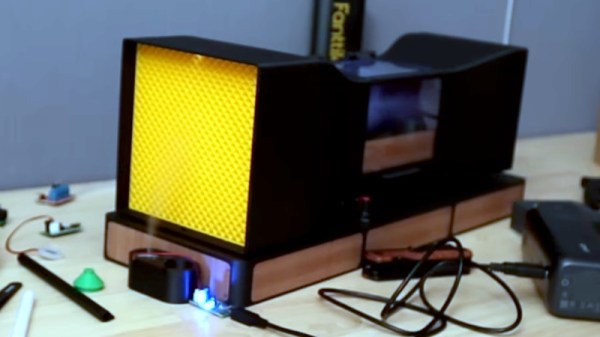
There’s a build video that we’ve embedded below, and if you can sit through the continuous shilling of random tools, it’s an interesting watch. It’s an open design in that air is not recirculate through it, instead it passed through the machine from left to right. On the right is the fan, on the left the intake with a rectifier to ensure laminar flow. Then a constriction compresses and speeds up the air past the stage for the model under test, and an expansion slows it down again for the fan.

A wind tunnel needs a smoke generator to easily spot turbulence, and in this case a vape is called into action. The result is surprisingly effective, as we see with a demonstration using a small model car. Meanwhile if you’re interested in wind tunnels at this size, it’s not the first one we’ve brought you.

Continue reading “See Aerodynamics In Action With A Desktop Wind Tunnel”

Building A Device To Map Magnetic Fields

Magnetic fields are all around us. We can’t really feel or see them ourselves, per se, but we can map them with the right hardware, like this device built by [edosari50].

The build uses an ESP32 microcontroller, which is built on to a board with an integrated 4.3″ touchscreen LCD. It’s paired with an Arduino Nano, which does the work of actually talking to a pair of EMS100 Fluxgate magnetic sensors. The slower, less capable Arduino handles the low-level chatter and then passes the readouts to the ESP32 over a UART connection. Power is courtesy of a pair of 18650 lithium-ion cells, and a XL4005 DC-DC converter. A lithium-ion charging module is on hand to keep the batteries topped off safely.  Scan results are visualized on the device itself using a heatmap representation, and can also be exported to SD card for later analysis if so desired.

Unless you’re in the geological field or otherwise hunting for stuff underground, this probably isn’t a tool you’ll have a lot of use for. However, if you like finding magnetic anomalies and investigating them, it might be very much in your wheelhouse. We’ve featured other tools for magnetic visualization before, too. Video after the break.
Continue reading “Building A Device To Map Magnetic Fields”

A mechanism made of brass and steel is attached to a milling machine. It has a long lever extending from the right side, a counterweight attached to the left side, and an indicator gauge in the middle.

A Precision Drill Press For Tiny Bits

Anyone who’s worked with even a 1 mm bit knows that while a drill press is all but essential, it isn’t proof against broken bits. Working with a 0.1 mm drill bit seems, therefore, all but impossible, which is why [Mike] of Chronova Engineering built this mechanism to simplify such drilling.

The mechanism is an attachment for a milling machine, and in principle it just needs to move the rotating drill bit up and down. It needs to be extremely precise, though. For context, a good-quality chuck normally has a runout of 30 to 50 microns, which is approaching half the diameter of the drill bit. The mechanism has a collet mounted in the milling machine’s spindle, which transfers rotation to a second spindle. The second spindle is mounted to a runout-compensating drill chuck, and is connected to a lever and counterweight which allow the user to make small, low-force movements. A dial indicator lets the user see how far the bit’s descended.

Most of the parts were machined out of steel or brass, with the handle being made of titanium for lower weight. When the finished device was mounted to the milling machine, the measured runout was severe. After much investigation and reworking, however, the problem turned out to be a damaged collet locating pin, not an issue with the drilling mechanism. As a first test, [Mike] drilled a 0.1 mm hole 1.8 mm deep, then as a challenge drilled six 0.1 mm holes in the end of a thin steel wire. The results weren’t quite as uniform as he wanted, but it took a scanning electron microscope to even see the imperfection.

It won’t help much with very fine drill bits, but if you need a very precisely-placed hole, check out this periscopic drilling camera. If you do break a drill bit in the workpiece, you might be able to dissolve it with alum.

Continue reading “A Precision Drill Press For Tiny Bits”

Building A Die Filer From Scratch

A die filer is a useful tool to have if you find yourself filing parts on the regular. It’s basically a machine that reciprocates a file up and down for you so you can focus on filing the part to your desired dimensions. They’re not commonly manufactured these days, so [Richard Huberjohn] set about building his own. 

This die filer relies on a simple mechanism to turn rotational motion from a motor into reciprocating linear motion in the vertical plane. A rotating shaft is connected to a crank, which turns a pin in a slotted carrier attached to a linear bearing. As the wheel turns, the pin slides in the carrier, driving it and the linear rod up and down in turn. Attach a file to this, and you have a working die filer. In this case, the rotating shaft is driven by a pair of DC brushed motors, with output stepped down via a gearbox and then a short belt drive. Speed is varied with the aid of an off-the-shelf controller.

If you’re regularly filing small parts, a build like this could speed your work to a great degree. We’ve featured other DIY machine tool builds before, too. If you’re cooking up your own gear for the home workshop, don’t hesitate to let us know on the tipsline!

A fine steel gear is shown held between a man's fingertips.

Cutting Steel Gears With Homemade EDM

Electric discharge machining (EDM) may be slower than alternatives like laser cutting, water jets, or a milling machine, but for some applications there’s no alternative: it can cut through any conductive material, no matter how hard, and it leaves no mechanical or thermal stress in the workpiece. Best of all, they’re relatively accessible for a resourceful hacker, such as [Inofid], who recently built the second iteration of his desktop wire EDM.

The EDM’s motion system comes from a cheap desktop CNC router, which had a water tank mounted in its workspace and had the spindle replaced with a wire-management mechanism. The wire-management mechanism needs to continuously wind a tensioned brass wire from one spool through the cutting zone onto another spool. The tensioning system uses two motors: one to pull the wire through, and one to maintain tension by slightly counteracting it, with a tension sensor and Ardunio to maintain the proper tension. If it detects that the wire has broken, it can stop the CNC controller. To keep the wire from breaking or short-circuiting with the workpiece, a current monitor counts sparks between the wire and workpiece and uses this to predict whether the wire is getting too close to the metal, in which case it slows down the movement.

As a first test, [Inofid] cut through a five by three centimeters-thick block of aluminium, taking two hours but producing a clean cut. To speed up the next cut, [Inofid] added a pump and filter to remove sludge from the cutting area. The next cut was an aluminium gear, and then a meshing steel gear, which took about ten hours but turned out well.

EDMs of various kinds appear here from time to time, particularly since the popularization of 3D printers. We’ve even seen one built into a lathe.

Thanks to [Keith Olson] for the tip!

This KiCAD Plugin Enables Breadboarding

Some people learning the noble art of electronics find the jump from simpler tools like Fritzing to more complex ones, such as KiCAD, a little daunting, especially since they need to learn at least two tools. Fritzing is great for visualising your breadboard layout, but what if you want to start from a proper schematic, make a prototype on a breadboard and then design a custom PCB? Well, with the Kicad-breadboard plugin for (you guessed it!) KiCAD, you can now do all of this in the same tool.

A simple dual-rail oscillator schematic corresponding to the featured image above

Originally designed to support EE students at the University of Antwerp, the tool presents you with a virtual breadboard with configurable size and style, along with a list of components and tools that can be placed. A few clicks and parts can be placed on the virtual breadboard with ease. Adding wires is the next logical step to make those connections that operate in the horizontal dimension. Finally, assigning power supplies and probe connections completes the process. It’s a simple enough tool to draw stuff, but drawing a layout is no use if you can’t verify it’s correctness. This is where this plugin shines: it can perform an ERC (check) between the schematic and the breadboard and flag up what you missed. Add to this that you can also perform an ERC at the schematic level, before even thinking about layout, and it’s pretty hard to make an error. Now, you can transfer this directly to a real breadboard, or even a veroboard, for more permanence once you have confidence in correctness. This will definitely save time correcting errors and help keep the magic smoke safely contained within those mysterious black rectangles.

Continue reading “This KiCAD Plugin Enables Breadboarding”

The Splice Must Flow

There are plenty of electronic components out there, but the one we tend to forget is the most basic: wire. Sure, PC boards have largely replaced wire with copper traces, but most projects still need some kind of wire somewhere. Once you need any wire, there’s a good bet you will need longer wire, and that means splicing one wire to another. Simple, right? Not really. There are a variety of ways to splice wires, and which one you use depends on what you want to do and the type of wire you are using.

If the wires touch, good enough, right? Not necessarily. You need enough contact area for the current you are drawing through the wire to flow. It is also nice if the splice can survive some amount of mechanical strain, vibration, and survive getting hot and cold repeatedly.

Usually, after splicing, you’d like to solder the connection, although depending on the application, you don’t always see that. At the very least, you’d want to wrap it in electrical tape, use heat-shrink tubing, or otherwise insulate the bare wires and maybe provide a little mechanical support or strain relief.

Keep in mind that there are connector options, either mechanical, crimped, or soldered, that allow you to avoid splices. Soldering to a terminal strip, for example, or scewing wires into a barrier strip will get the job done. So will a butt connector, a wire nut, or a WAGO connector. But sometimes, for whatever reason, you just need to attach two wires to each other. It’s been done before.

Continue reading “The Splice Must Flow”