Teardown Of A (Relatively) Cheap Thermal Camera

The cost of tools and test equipment has largely been on the downward trend for years, making it now more affordable than ever to get into the hacking and making scene. This is particularly visible with something like the venerable oscilloscope: a piece of equipment that was near unobtainium for the home hacker a decade ago, you can now get digital pocket scope for as little as $20 USD. But there are still pieces of gear which haven’t quite hit the sort of prices we’d like to see.

A perfect example are thermal imaging cameras. The cheap ones are usually so low resolution they might as well just be thermometers, but the higher resolution ones can cost thousands. [Rob Scott] recently wrote in to tell us about a very promising middle ground, the HTI HT-A1. But he didn’t just point it out to us, he also tore it down and laid its internal’s bare for our entertainment. Now that’s our kind of introduction.

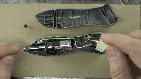
[Rob] walks us through the disassembly of the device, which is made unnecessarily difficult due to the fact that half the screws are hidden under a glued on screen bezel. That means a heat gun, a thin tool, and patience are in order if you want to get inside the device. It’s bad enough they use these kinds of construction techniques on modern smartphones, but at least they’re so thin that we can understand the reasoning. Why this chunky thing needs to resort to such measures is beyond us.

Eventually he cracks the HT-A1 open and is greeted with a single double-sided PCB. The top side is pretty much bare except for the buttons and the LCD display, and the flip side is largely just a breakout for a quad-core Allwinner A33 daughterboard. [Rob] theorizes this is to keep costs down by allowing reuse of the modular A33 board on other devices. Given the A33’s use in so many cheap tablets, it’s also possible HTI simply purchased these daughterboards as a drop-in component and designed their own board around it.

There’s not much else inside the HT-A1 beyond the rechargeable battery pack and thermal camera, both attached to the device’s rear panel. [Rob] noticed that the date on the thermal camera PCB is a full two years older than the date on the main PCB, leading one to wonder if HTI might have gotten a good deal on a bunch of these slightly outdated sensors and spun up a whole device around them.

The HT-A1 is high enough resolution that you can actually pick out individual components on a PCB, and at $400 USD is approaching a reasonable price point for the individual hacker. Which is not to say it’s cheap, but at least you get a useful tool for your money. We wouldn’t suggest you buy this device on a whim, but if you do a lot of diagnostic work, it might pay for itself after a couple repairs.

If that’s still a little too rich for your blood, we’ve covered a handful of DIY options which might better fit your budget.

Continue reading “Teardown Of A (Relatively) Cheap Thermal Camera”

Homebrew Attachment Turns Angle Grinder Into Slimline Belt Sander

If there’s a small power tool as hackable as the angle grinder, we haven’t found it yet. These versatile tools put a lot of power in the palm of your hand, and even unhacked they have a huge range of functionality, from cutting to grinding to polishing and cleaning, just by choice of what goes on the arbor.

With a simple homebrew attachment, [Darek] turned his angle grinder into a micro-belt sander that’s great for those hard-to-reach places. The attachment that clamps where the disc guard normally lives adds a drive roller to the grinder’s arbor; idler rollers ride on the end of a small pneumatic spring that keeps the belt under tension. The belts themselves are cut down from wider sanding belts, and the attachment can take belts of various widths. And best of all, he did it all without any fancy machine tools. No lathe? No problem – the drive roller was ground to the proper crowned profile needed to keep belts centered using the angle grinder itself. The only problem we see is that the attachment can’t be easily removed from the grinder, but that’s OK. Grinders are like potato chips, after all – you can’t stop at one.

This isn’t [Darek]’s first angle grinder hacking rodeo, of course. And if you’re looking for inspiration on how to hack yours, look no further: a floor sander, a precision surface grinder, or even an e-bike can be built.

Continue reading “Homebrew Attachment Turns Angle Grinder Into Slimline Belt Sander”

Scratch Built Toe Clamps Keep Your Work In Place

[Kevin] owns a benchtop CNC mill that has proven itself to be a capable tool, but after becoming familiar with some of its shortcomings, he has made a few modifications. In order to more efficiently hold and access workpieces on his custom fixturing table, he designed and made his own toe clamps and they look beautiful.

The usual way to secure a piece of stock to a fixturing table is to use top-down clamps, which hold the workpiece from the top and screw down into the table. However, this method limits how much of the stock can be accessed by the cutting tool, because the clamps are in the way. The most common way around this is to mount a vise to the table and clamp the workpiece in that. This leaves the top surface completely accessible. Unfortunately, [Kevin]’s benchtop Roland MDX-450 has a limited work area and he simply couldn’t spare the room. His solution was toe clamps, which screw down to the table and have little tabs that move inwards and downward. The tabs do the work of clamping and securing a piece of stock while maintaining a very low profile themselves.

The clamp bases are machined from stainless steel and the heads are brass, and the interface between the two is a set screw. Inserting a hex wrench and turning the screw moves the head forward or back, allowing a workpiece to be clamped from the sides with minimal interference. His design was done in Fusion 360 and is shared online.

Another option for when simple clamps won’t do the job is a trick from [NYC CNC], which is to use an unexpected harmony of blue painter’s tape and superglue which yields great results in the right circumstances.

Flexible Battery Meter Bends Over Backward To Work

A lithium-ion battery tester seems like a simple project, at least electrically. But when you start thinking about the physical problem of dealing with a huge range of battery sizes, things get a little more complicated. Sure, you can 3D-print adapters and jigs to accommodate the different batteries, or you can cheat a bit and put the charger and tester circuit on a flexible PCB.

Maybe it’s the Kapton talking, but we really like the look of [Androkavo]’s project. The idea is simple – rather than use a rigid FR4 printed circuit board, a flexible polyimide film PCB a little longer than the biggest battery to be tested was fabricated. With large contacts on each end, the board can just be looped across the battery to take a reading. For charging, neodymium magnets on the other side of the board keep the charger in contact with the battery. The circuit itself is built around an STM8S003 8-bit microcontroller and a handful of discrete components. There’s a bar graph display for battery voltage that covers 2.0 to 4.9 volts, and a USB port for charging. The charger works with everything from the big 21700 cells down to the short 14500s. With the help of another magnet to keep the board from bending too sharply, even the diminutive 10180 can be charged. Check out the video below, which has some of the most relaxing music and best microscope shots of SMD soldering we’ve seen.

Flexible PCBs are versatile things. Not only can they make projects like this successful, but they can also wriggle around, swim, or even play music.

Continue reading “Flexible Battery Meter Bends Over Backward To Work”

Cut Through The Noise, See Tiny Signals

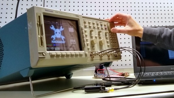
An oscilloscope is a handy tool for measuring signals of all kinds, but it’s especially useful if you want to measure something with a periodic component. Modern oscilloscopes have all kinds of features built-in that allow you sample a wide range of signals in the hundreds of megahertz, and make finding and measuring your signal pretty easy, provided you know which buttons to push. There are some advanced oscilloscope methods that go beyond the built-in features of even the best oscilloscopes, and [AM] has a tutorial on one of them.

The method used here is called phase-senstitive detection, and allows tiny signals to be found within noise, even if the magnitude of the noise is hundreds of times greater than the signal itself. Normally this wouldn’t be possible, but by shifting the signal out of the DC range and giving it some frequency content, and then using a second channel on the oscilloscope to measure the frequency content of the source and triggering the oscilloscope on the second channel, the phase of the measured signal can be sifted out of the noise and shown clearly on the screen.

In [AM]’s example, he is measuring the intensity of a laser using a photodiode with a crude amplifier, but even with the amplifier it’s hard to see the signal in the noise. By adding a PWM-like signal to the power source of the laser and then syncing it up with the incoming signal from the photodiode, he can tease out the information he needs. It’s eally a fascinating concept, and if you fancy yourself a whiz with an oscilloscope this is really a tool you should have in your back pocket.  If you’re new to this equipment, we do have a primer on some oscilloscope basics, too.

Continue reading “Cut Through The Noise, See Tiny Signals”

The Modern Analog Soldering Station

There is a certain sense of accomplishment one gets when building their own tools. This is what [Alejandro Velazquez] was going for when he built his own soldering station. Sure you can get a decent station for a pittance on Amazon, or eBay. You can even build your own microprocessor controlled station. [Alejandro] is currently interested in analog electronics, so he went that route to build his own closed-loop station.

The handle is a 50 watt, 24-volt affair with a thermocouple. You can find this handle on many Hakko 907 clone soldering stations, often referred to as the 907A. The station itself is completely analog. A triac switches the current going to the heater. The triac is controlled by a PWM signal. The PWM itself is generated and regulated by an LM324 quad op-amp, which is the heart of the station. The op-amp compares the setpoint with the current temperature read from the soldering handle’s thermocouple, then adjusts the duty cycle of the PWM signal to raise, or lower the temperature.

It’s a classic control system, and the schematic is definitely worth checking out if you want to understand how op-amps can be used to create complex operations.

You can find plenty more information on analog electronics right here on Hackaday — we’ve covered thermocouple amplifiers, as well as instrumentation amps. If you’re more of a digital man, check out this Arduino controlled soldering station!

The Machinists’ Mantra: Precision, Thy Name Is Rigidity

“Everything is a spring”. You’ve probably heard that expression before. How deep do you think your appreciation of that particular turn of phrase really is? You know who truly, viscerally groks this? Machinists.

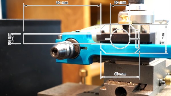
As I’ve blathered on about at length previously, machine tools are all about precision. That’s easy to say, but where does precision really come from? In a word, rigidity. Machine tools do a seemingly magical thing. They remove quantities of steel (or other materials medieval humans would have killed for) with a slightly tougher piece of steel. The way they manage to do this is by applying the cutting tool to the material within a setup that is so rigid that the material has no choice but to yield. Furthermore, this cutting action is extremely precise because the tool moves as little as possible while doing so. It all comes down to rigidity. Let’s look at a basic turning setup.

Continue reading “The Machinists’ Mantra: Precision, Thy Name Is Rigidity”