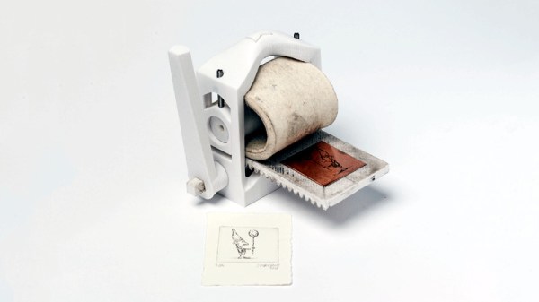
When a fine piece of lab instrumentation crosses your bench, you’ve got to do your best to put it to work. But even in the highest quality devices no component lasts forever, especially vacuum tubes. For some vintage instruments with vacuum fluorescent displays, that means putting up with less-than-perfect digits in order to get that sweet, sweet precision. Or not – you can always reverse engineer the thing and add a spanking new OLED display.
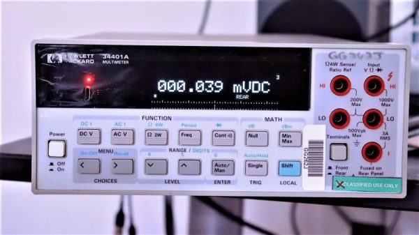
The Hewlett-Packard 34401A digital multimeter that fell into [qu1ck]’s lap was a beauty, but it had clearly seen better days. The display was full of spuriously illuminated dots and segments, making it hard to use the 6.5 digit DMM. After a futile bit of probing to see if a relatively easy driver fix would help, and with a replacement display being made of solid unobtanium, [qu1ck] settled in for the long process of reverse engineering the front panel protocol. As luck would have it, H-P used the SPI protocol to talk to the display, and it wasn’t long before [qu1ck] had a decent prototype working. The final version is much more polished, with a display sized to fit inside the original space occupied by the VFD. The original digits and annunciator icons are recreated, and he added a USB port and the bargraph display show in the clip below.
We think it looks fabulous, and both the firmware and hardware are on Github if you’d like to rescue a similar meter. You may want to check our guide to buying old test gear first, though, to get the most bang for your buck.
 The full MatchSticks creation flow goes like this:
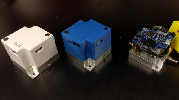
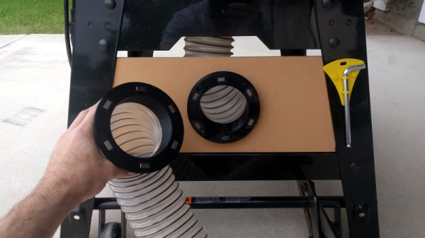
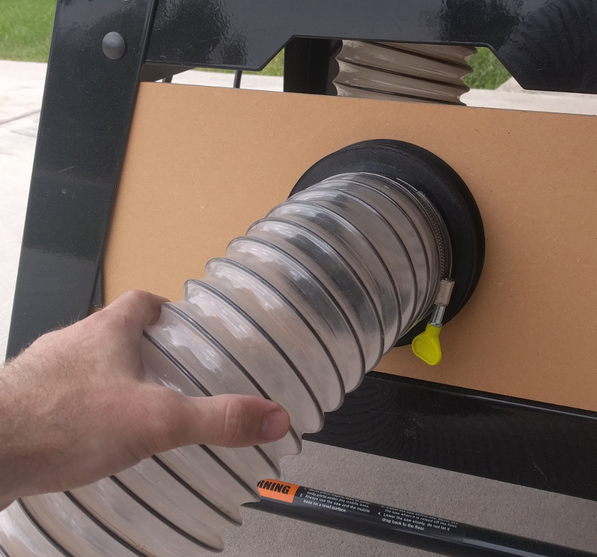
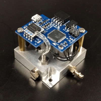 For many projects that require control of air pressure, the usual option is to hook up a pump, maybe with a motor controller to turn it on and off, and work with that. If one’s requirements can’t be filled by that level of equipment and control, then it’s time to look at commercial regulators. [Craig Watson] did exactly that, but found the results as disappointing as they were expensive. He found that commercial offerings — especially at low pressures — tended to leak air, occasionally reported incorrect pressures, and in general just weren’t very precise. Out of a sense of necessity he set out to design his own