Homebrew Curve Tracer Competes With The Big Guns

When we first saw the VBA curve tracer, we thought it might have something to do with Visual Basic for Applications. But it turns out it is a mash up of the names of the creators: [Paul Versteeg], [Bud Bennett], and [Mark Allie]. [Paul] designed an original prototype back in 2017. Since then, the project has grown and lessons were learned. The final curve tracer is pretty impressive in more ways than one.

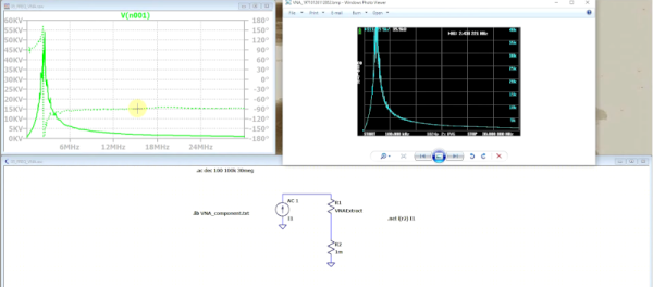
If you’ve never used a curve tracer, they allow you to characterize components using their characteristic curve of voltage versus current. You use an oscilloscope as an output device. This instrument is often used by engineers trying to understand or match devices like diodes, transistors, or — in some cases — even tubes. So if you want to measure the collector-emitter breakdown voltage, for example, or the collector cutoff current, this is your go-to device. You can also match gains in circuits where that matters (for example, a push-pull circuit where two transistors amplify different parts of the same signal).

If you want to understand more about how it works, there are a series of blog posts covering the evolution of the device. You can also find the design files on GitHub. There is also a handy post showing many types of measurements you might want to make.

This is a good-looking project. We’ve seen it done on the cheap, but slowly. Or spend $15 and do better. We doubt any of these have high enough voltages to do most tubes, but they made the same basic instrument for tubes back in the 1950s.

Cut Just About Anything With This Combination Lathe And Wire EDM

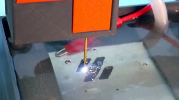
They say that if you have a lathe, you have every other machine tool too. To some degree, that’s true — you can make almost anything on a lathe, including another lathe, and even parts best made on other machine tools can usually be made on a lathe in a pinch. But after seeing this lathe attachment for a DIY electric discharge machining tool, we might be inclined to see the EDM as the one machine tool to rule them all.

Now, we’ll admit that the job [BAXEDM] built this tool for might be a little contrived. He wanted to make some custom hex inserts for his Swiss Army knife, which seem like they’d have been pretty easy to make from hex bar stock in a conventional lathe. Then again, hardened steel is the kind of material that wire EDM was made for, and there seem to be many use cases for an attachment that can spin a workpiece against an EDM cutting wire.

That was really the trick of this build — spinning a part underwater. To accomplish this, [BAXEDM] built a platform to carry a bearing block that supports a standard ER-25 collet, with a bracket that holds a stepper clear of the water in the EDM cutting tank. There are plenty of 3D printed insulators too, to keep most of the attachment electrically isolated from the EDM current, plus exotic parts like ceramic bearings that won’t corrode under water. There were a ton of other considerations, too; [BAXEDM] goes through the long iterative design process in the video below, as well as taking his new tool for a literal spin starting at about the 27:00 mark.

If you’re intrigued by what EDM can accomplish — and who wouldn’t be? — but you need more background on the process, we’ve got you covered.

Continue reading “Cut Just About Anything With This Combination Lathe And Wire EDM”

Programmable Resistance Box

For prototype electronics projects, most of us have a pile of resistors of various values stored somewhere on our tool bench. There are different methods of organizing them for easy access and identification, but for true efficiency a resistance substitution box can be used on the breadboard to quickly change resistance values at a single point in a circuit. Until now it seemed this would be the pinnacle of quickly selecting differently-sized resistors, but thanks to this programmable resistor bank there’s an even better option available now.

Unlike a traditional substitution box or decade box, which uses switches or dials to select different valued resistors across a set of terminals, this one is programmable and uses a series of sealed relays instead. That’s not where the features stop, though. It also comes equipped with internal calibration circuitry which take into account the resistance of the relay contacts and internal wiring to provide a very precise resistance value across its terminals. It’s also able to be calibrated manually to account for temperature or other factors.

For an often-overlooked piece of test equipment, this one surely fits the bill of something we didn’t know we needed until now. Even though digital resistor substitution boxes are things we have featured in the past, the connectivity and calibration capabilities of this one make it intriguing.

Putting A Cheap Laser Rangefinder Through Its Paces

Sometimes a gizmo seems too cheap to be true. You know there’s just no way it’ll work as advertised — but sometimes it’s fun to find out. Thankfully, if that gadget happens to be a MILESEEY PF210 Hunting Laser Rangefinder, [Phil] has got you covered. He recently got his hands on one (for less than 100 euros, which is wild for a laser rangefinder) and decided to see just how useful it actually was.

The instrument in question measures distances via the time-of-flight method; it bounces a laser pulse off of some distant (or not-so-distant) object and measures how long the pulse takes to return. Using the speed of light, it can calculate the distance the pulse has traveled).

As it turns out, it worked surprisingly well. [Phil] decided to focus his analysis on accuracy and precision, arguably the most important features you’d look for while purchasing such an instrument. We won’t get into the statistical nitty-gritty here, but suffice it to say that [Phil] did his homework. To evaluate the instrument’s precision, he took ten measurements against each of ten different targets of various ranges between 2.9 m and 800 m. He found that it was incredibly precise (almost perfectly repeatable) at low distances, and still pretty darn good way out at 800 m (±1 m repeatability).

To test the accuracy, he took a series of measurements and compared them against their known values (pretty straightforward, right?). He found that the instrument was accurate to within a maximum of 3% (but was usually even better than that).

While this may not be groundbreaking science, it’s really nice to be reminded that sometimes a cheap instrument will do the job, and we love that there are dedicated folks like [Phil] out there who are willing to put the time in to prove it.

Print Your Own Drill Guide Without A Linear Bearing

Typically we often don’t cover paid products here on Hackaday, but we couldn’t help but be impressed with this 3D printed drill guide from [USSA]. While you’ll need to pay the toll to access the STL files and plans, there’s an excellent video showing a bit of magic behind the curtain that you can check out free of charge. There are several interesting insights and some great techniques put into this design that anyone could take and apply to their own project.

First, what is a drill guide? Many of us don’t have the luxury of a full-sized drill press, so we have to make do with a hand drill. There are various jigs and tricks to get straighter holes, but it can be frustrating to mark out threaded screw inserts with great precision only to discover all the inserts are at an angle and the circuit board won’t fit. A drill guide ensures holes are plunged straight up and down and at a reliable depth.

[USSA] starts by showing the node-based CAD that makes up the design (a program called Grasshopper). As he assembled it, simple nuts and screws held it together. But rather than clamp two separate pieces together, the screws compress the single plastic with a clever slot in the side to allow the plastic to flex. Several 3D printed jigs were used for assembling the bearing shaft. Ultimately the results look quite impressive, and it’s an inspiration for our own printed projects.

Continue reading “Print Your Own Drill Guide Without A Linear Bearing”

Beautiful Inductors, Now Not Such A Lost Art

As ferrite technology has progressed into a mastery of magnetic permeability, the size of inductors has gone down to the point at which they are now fairly nondescript components. There was a time though when inductors could be beautiful creations of interleaving layers of copper wire in large air-cored inductors, achieved through clever winding techniques. It’s something that’s attracted the attention of [Brett], who’s produced a machine capable of producing something close to the originals.

Part of the write-up is an investigation of the history, these coils were once present even at the consumer level but are now the preserve of only a few highly secretive companies. They are still worth pursuing though because they can deliver the high “Q” factor that is demanded in a high quality tuned circuit. The rest of the write-up dives in detail into the design of the wire feeder, and the Arduino motor control of the project. There should be enough there for any other experimenters to try their hands at layered inductors, so perhaps we’ll see this lost art make a comeback.

Custom coils are a regular requirement for anything from radios, to musical instruments, to switching power supplies, so it’s not surprising that quite a few projects featuring them have made it here. One of the more unusual of late has been one that winds toroids.

A Home Made Sewing Machine May Be The Only One

The sewing machine is a tool that many of us will have somewhere around our workshop. Concealed within it lies an intricate and fascinating mechanism. Some of us may have peered inside, but very few indeed of us will have gone to the effort of building our own. In case you had ever wondered whether it was possible, [Fraens] has done just that, with what he claims may be the only entirely homemade sewing machine on the Internet.

If you’ve ever studied the history of sewing machines you’ll notice that it bears a striking resemblance to some of the earliest commercial machines, with a relatively short reach and an entirely open construction. The main chassis appears to be laser-cut acrylic while all the fittings are 3D-printed, with machined brass bushes and aluminum rods for the other metal parts. The design utilizes a hand crank, but is also pictured with a DC motor. It makes for a fascinating illustration of how sewing machines work. Sadly we can’t see any design file links (Update: He’s contacted us to tell us they’re now on Thingiverse.), so you might have to be inventive if that’s the way you want to build your own. Take a look at it in the video below the break.

Fancy a sewing machine but don’t fancy making your own? We’ve got the guide for that, and for filling the rest of your textile bench.

Continue reading “A Home Made Sewing Machine May Be The Only One”