Around the world, governments and city planners have long struggled with the issue of transport. Getting people where they need to be in a timely fashion is key to making a city a comfortable, attractive place to live. As far as public transport is concerned, this typically consists of buses on the roads, and trams and trains on rails.
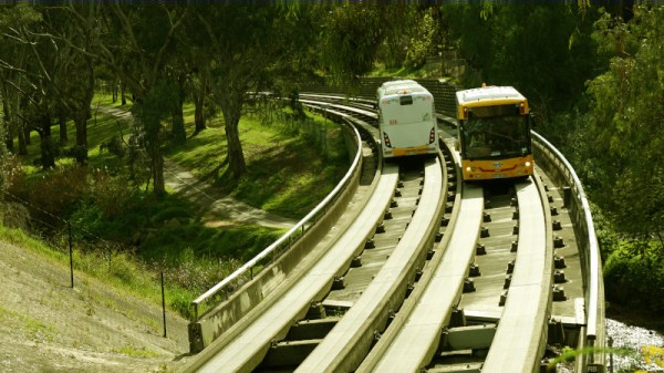
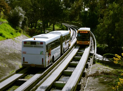
Down in the city of Adelaide, Australia, things get a little muddled, however. Nestled in a river valley lies a special transportation network known as the O-Bahn, where buses ride on concrete rails and the drivers can even take their hands off the wheel. The system remains a rarity worldwide, and was spawned by a perfect storm of conflicting requirements.
A Child of Circumstance
In the 1970s, the South Australian government found itself backed into a corner. Facing a booming population in the north-eastern suburbs, new transport links with greater capacity were needed to get people to the central business district. Original plans from the 1960s had called for more freeways to be built all over the city to solve the problem. In the face of stiff public opposition, legislation was passed in 1970 blocking the construction of any new freeways for a full decade, forcing the government to consider alternatives.
Despite plans being shelved, a corridor of land stretching from the city to the north-east had already been acquired for freeway construction. This was retained, and studies were commissioned to determine the best transportation solution to suit the needs of the area. The “North East Adelaide Public Transport Review” suggested light-rail or a busway would be the best solution.
Initial plans were proposed to link the north-east with a light-rail tramway that would connect with the existing tramline from the city proper to Glenelg in the west. However, the City of Adelaide protested the plan, believing that extending the existing tramline to the east would damage the city’s carefully planned structure. Plans were made to rectify this by running part of the line underground, massively increasing costs, and the proposal was shelved.
It was at this time, the guided busway in Essen, Germany came to the attention of the state government. Aiming to help reduce congestion by allowing buses to share tram tunnels, it began as a demonstration which later developed into the Spurbus network. The system offered lower cost and higher flexibility than light rail, and avoided the need to carve up the city to hook in to the existing light rail network. Had Adelaide laid out its existing heavy or light rail networks differently, the O-Bahn might not have gotten a look in. However, back in the early 1980s, it was an easy solution in a sea of difficult choices.
Continue reading “The O-Bahn Busway – Obscure Transit For The Masses”