Home Made 8mm Digitizer

The 8mm film look is making a comeback, but distributing it is an issue. [Heikki Hietala] wanted an easy way to digitally capture the 8mm movies he made. So, he built an 8mm digitizer from an Arduino, a cheap Canon camera and the guts of an old 8mm film camera. When you throw in a few 3D printed components and some odd electronics, you get an impressive build that captures 8mm film with impressive speed and quality.

This build started with a Canon Ixus 5 camera running CHDK (the Canon Hack Development Kit) to lock the settings down. This points at the film strip through a macro lens so each frame of the strip fills the frame. An Arduino then triggers the camera to take a photo using a USB cable. The same Arduino also controls a motor that winds the film and triggers the film gate from the camera that he salvaged. By reversing the function and triggering it with a servo motor, he can easily blank off the edges of the frame so no stray light shining through the film material causes any problems. Once the camera has captured every frame on the strip, he feeds the captured images into Blender, which processes them and spits out the final movie.

This is a very impressive build overall. [Heikki] has obviously put a lot of thought into it, and the whole thing looks like it runs very efficiently and quickly. The captured video looks great, as you can see from this sample. The decision to use a salvaged film gate was a smart one: there is no point in reinventing the wheel if engineers of previous generations have solved the problem. Kudos to [Heikki] for also documenting the process in a lot of detail: he has produced a 5-part series on his blog that shows how and why he made the decisions he did. This series goes over the overall view of the project, using CHDK to control the camera, 3D printing parts, wiring the Arduino and writing the code that controls the system.

This sits nicely alongside the 8mm to video camera hack that we wrote about recently. This one doesn’t involve taking apart the camera (except for the sacrificial one that supplied the gate), and you still get that wonderfully grainy, jumpy look of 8mm film.

Continue reading “Home Made 8mm Digitizer”

Retrotechtacular: Eidophor, An Unknown Widely Used Projector

If you own a video projector, be it a module small enough to fit in a mobile phone or one designed for a cinema screen, the chances are it will have a DLP at its heart. An array of microscopic mirrors on an integrated circuit, the current state of the art in video projection technology.

Perhaps you own an older video projector, or maybe a cheaper new one. If so the chances are it’ll have a small LCD screen doing its work, taking the place of the Kodachrome in something very similar to your grandparents’ slide projector or their grandparents’ magic lantern.

eidophore-patent-image-600pxLCD technology was invented in the 1970s, while DLP was invented at the end of the 1980s. So how did the video projectors that were such a staple of televised spectaculars in the preceding decades work? For that matter, how did NASA project their status displays on the huge screen at Mission Control? Certainly not with CRT technology, even the brightest CRT projectors weren’t up to filling a cinema-sized screen.

The answer came from the Eidophor (Greek: ‘eido’ and ‘phor’, ‘image’ and ‘bearer’), a device invented in the years before World War II by the Swiss physicist Dr. Fritz Fischer and granted a US patent in 1945. It featured a complex vacuum device in which an electron gun painted the video frames as a raster on an oil-covered mirror in the light path of a fairly conventional projector. High-voltage electric charges have the effect of deforming the surface of mineral oils, and it was this effect that was exploited to vary the effectiveness of the mirror as the raster was drawn. An unfortunate side-effect of tracing an oil surface with an electron beam is that a charge will build up on the oil surface, so the entire oil-covered mirror assembly had to rotate within its vacuum enclosure and pass under an electrode which removed any charge build-up.

Eidophor-wikipedia
Eidophor [by Topquark2 CC-BY-SA 3.0]
The resulting machine as seen in this 1952 issue of Popular Science was very large, complex, and expensive to run, but delivered by far the brightest and sharpest projected video available. In a literal sense they painted the backdrop to our culture, as they found a home not only in NASA’s control room but in television studios and at large televised events. This Shirley Bassey performance from the 1960s for example, or the spectacular video light show on this rather poor quality VHS YouTube clip from Seville Expo 1992.

You will probably be unaware of the exact date you last saw an eidophor performance. Quince Imaging tell us their last one was used at the TWA Dome in St Louis in July 2000. Eidophores may have become more compact over the decades but they remained costly to run, and through the 1990s they were suplanted by DLP devices that did substantially the same job with a lot less fuss.

It is not often that a search in the Hackaday archives for a technology returns no results, but the eidophor is one of those cases. Perhaps that is a fitting epitaph for a device that created its own show but never starred in it, that it is only its spectacular performances that live on.

Adventures In Small Screen Video

[Kevin] wanted to make something using a small CRT, maybe an oscilloscope clock or something similar. He thought he scored big with a portable black and white TV that someone threw away, but it wouldn’t power on. Once opened, he thought he found the culprit—a couple of crusty, popped capacitors. [Kevin] ordered some new ones and played with the Arduino TVout code while he waited.

The caps arrived, but the little TV still wouldn’t chooch. Closer inspection revealed that someone had been there before him and ripped out some JST-connected components. Undaunted, [Kevin] went looking for a new CRT and found a vintage JVC camcorder viewfinder on the electronic bay with a 1-1/8″ screen.

At this point, he knew he wanted to display the time, date, and temperature. He figured out how the viewfinder CRT is wired, correctly assuming that the lone shielded wire is meant for composite video. It worked, but the image was backwards and off-center. No problem, just a matter of tracing out the horizontal and vertical deflection wires, swapping the horizontal ones, and nudging a few pixels in the code. Now he just has to spin a PCB, build an enclosure, and roll his own font.

[Kevin]’s CRT is pretty small, but it’s got to be easier on the eyes than the tiniest video game system.

Bullet-time Video Effect By Throwing Your Phone Around

Ski areas are setting formal policies for drones left and right, but what happens when your drone isn’t a drone but is instead a tethered iPhone with wings swinging around you like a ball-and-chain flail as you careen down a mountain? [nicvuignier] decided to explore the possibility of capturing bullet-time video of his ski runs by essentially swinging his phone around him on a tether. The phone is attached to a winged carrier of his own design, 3D printed in PLA.

One would think this would likely result in all kinds of disaster, but we haven’t seen the outtakes yet, and the making-of video has an interesting perspective on each of the challenges he encountered in perfecting the carrier, ranging from keeping it stable and upright, to reducing the motion sickness with the spinning perspective, and keeping it durable enough to withstand the harsh environment and protect the phone.

He has open sourced the design, which works for either iPhone or GoPro models, or it is available for preorder if you are worried about catastrophic delamination of your 3D printed model resulting in much more bullet-like projectile motion.

Continue reading “Bullet-time Video Effect By Throwing Your Phone Around”

Color TV Broadcasts Are ESP8266’s Newest Trick

The ESP8266 is well known as an incredibly small and cheap WiFi module. But the silicon behind that functionality is very powerful, far beyond its intended purpose. I’ve been hacking different uses for the board and my most recent adventure involves generating color video from the chip. This generated video may be wired to your TV, or you can broadcast it over the air!

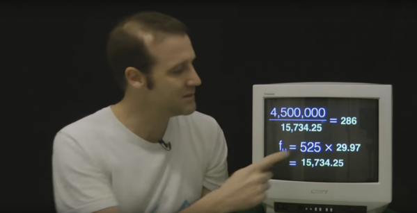
I’ve been tinkering with NTSC, the North American video standard that has fairly recently been superseded by digital standards like ATSC. Originally I explored pumping out NTSC with AVRs, which lead to an entire let’s learn, let’s code series. But for a while, this was on the back-burner, until I decided to see how fast I could run the ESP8266’s I2S bus (a glorified shift register) and the answer was 80 MHz. This is much faster than I expected. Faster than the 1.41 MHz used for audio (its intended purpose), 2.35 MHz used for controlling WS2812B LEDs or 4 MHz used to hopefully operate a reprap. It occasionally glitches at 80 MHz, however, it still works surprisingly well!

The coolest part of using the chip’s I2S bus is the versatile DMA engine connected to it. Data blocks can be chained together to seamlessly shift the data out, and interrupts can be generated upon a block’s completion to fill it in with new data. This allows the creation of a software defined bitstream in an interrupt.

Why NTSC? If I lived in Europe, it would have been PAL. The question you’re probably thinking is: “Why a dead standard?” And there’s really three reasons.

Continue reading “Color TV Broadcasts Are ESP8266’s Newest Trick”

VGA Output On A Freescale

Even though VGA is an outdated and becoming somewhat deprecated, getting this video output running on non-standard hardware is a rite of passage for some hackers. [Andrew] is the latest to take up the challenge. He got VGA output on a Freescale i.MX233 and also got some experience diving into the Linux kernel while he was at it.

The Freescale i.MX233 is a single-board computer that is well-documented and easy to wire up to other things without specialized hardware. It has video output in the form of PAL/NTSC but this wasn’t quite enough for [Andrew]. After obtaining the kernel sources, all that’s needed is to patch the kernel, build the kernel, and build a custom DAC to interface the GPIO pins to the VGA connector.

The first thing that [Andrew] did was load up the Hackaday home page, which he notes took quite a while since the i.MX233 only runs at 454 MHz with just 64 MB of RAM. While our retro page may have loaded a little faster, this is still an impressive build and a great first step to exploring more of the Linux kernel. The Freescale i.MX233 is a popular chip for diving into Linux on single-board computers, and there’s a lot going on in that community. There are some extreme VGA hacks out there as well if that’s more your style.