![[James] and his Lemontron portable 3D printer](https://hackaday.com/wp-content/uploads/2024/11/lemontron-1200.jpg?w=600&h=450)
What if your 3D printer could fit in a box of filament but still rival the build plate size of heavyweights? Enter the Lemontron, a free and open source portable printer making waves in the maker community for its compact form factor and budget-friendly price. Watch [James]’ video on his build story here. Built around the Positron drive—a unique mechanism introduced by [Kralyn] in 2022—the Lemontron is the latest evolution of this innovative design. Although Kralyn mysteriously disappeared, their work inspired other projects like the Positron JourneyMaker and this Lemontron.
The Lemontron started as a unibody chassis mod for the JourneyMaker but grew into a complete redesign, cutting costs in half without sacrificing performance. By eliminating expensive CNC parts, it’s entirely made from off-the-shelf components, bringing the build cost to just $413. Compare that to $800 for the JourneyMaker and $699 for the Positron v3.2 kit.
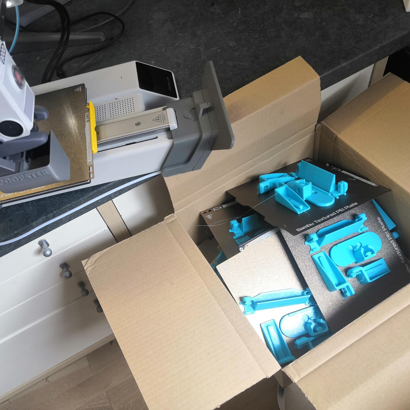
![Overhead photo of [James]' hands assembling the Lemontron Portable 3D printer](https://hackaday.com/wp-content/uploads/2024/11/My-3d-printer-is-almost-ready-to-release-16-56-screenshot.png?w=400) Recent video updates show the Lemontron in action, printing impressively large and complex models. It tackled a marble run with 80-degree unsupported overhangs and a ‘comically large’ Benchy, proving its capability. Its compact design, paired with robust performance, is an exciting alternative for tinkerers seeking quality on a budget.
Recent video updates show the Lemontron in action, printing impressively large and complex models. It tackled a marble run with 80-degree unsupported overhangs and a ‘comically large’ Benchy, proving its capability. Its compact design, paired with robust performance, is an exciting alternative for tinkerers seeking quality on a budget.
The Lemontron is in its final development stages, with frequent updates dropping on its YouTube channel. If you’re in the market for a more “traditional” mini-printer, check out this cool suitcase model from 2014.
Continue reading “If Life Gives You Lemons, Build This Lemontron”