In the early days of 3D printing, most people used ABS plastic. It is durable and sticks well to simple surfaces. However, it smells and emits fumes that may be dangerous. It also tends to warp as it cools which causes problems when printing. PLA smells nicer and since it is made from corn is supposed to be less noxious. However, PLA isn’t as temperature resistant and while it will stick better to beds without heat, it also requires more airflow to set the plastic as it prints. [Kerry Stevenson] recently reviewed PLA-F which is a blend of the two plastics. Is it the best of both worlds? Or the worst?
[Kerry] did several tests with interesting results. He did a temperature test tower and found the material printed well between 190 and 240 °C. He did note some stringing problems, though.
If we’re honest, our workshop isn’t as clean as it probably should be, and likely many makers out there will say the same. This can have knock-on effects, such as iron filings clogging motors, or in this case, dust affecting the quality of 3D prints. Aiming to tackle this, [3Demon] built a fun Spongebob-themed dust filter for their 3D printer.
The filter works in a simple way. The Spongebob shell is 3D printed in two halves, with a hinge joining both parts. Inside each half, a section of sponge is stuck inside. The two halves are then closed with a snap fit, with the filament passing through a hole in Spongebob’s head and out through the (square) pants. With the sponge packed in nice and tight, dust is wiped from the filament as it feeds through bob to the printer.
While it’s important to install carefully to avoid filament feed issues, it’s an easy way to automatically clean filament during the printing process. You may be surprised just how dirty your filament gets after sitting on the shelf for a few months. Getting rid of such contamination decreases the likelihood of annoying problems like delaminations and jams. Avid printers may also want to consider making their own filament, too. Happy printing!
This week our own [Donald Papp] wrote a thought-provoking piece on buying and selling 3D-printer models. His basic point: if you don’t know what you’re getting until you’ve purchased it, and there’s no refund policy, how can you tell if your money is being well spent? It’s a serious problem for these nascent markets, because when customers aren’t satisfied they won’t come back.
It got me thinking about my own experience, albeit with all of the free 3D models out there. They are a supremely mixed bag, and even though you’re not paying for the model, you’re paying in printing time, filament, and effort. It pays to be choosy, and all of [Donald]’s suggestions hold in the “free” market as well.
Only download models that have been printed at least once, have decent documentation about things like layer height, filament type, and support, and to the best of your abilities, be critical about the ability to fabricate the part at all. Fused-deposition printers can only print on top of previous layers, and have a distinct grain, so you need to watch out for overhangs and print orientation. With resin printers, you need to be careful about trapped volumes of uncured resin. You want to be sure that the modeler at least took these considerations into account.
But when your parts have strength requirements, fits, and tolerances, it gets even worse. There’s almost no way a designer can know if you’re overextruding on your first layers or not. Different slicers handle corners differently, making inner surfaces shrink to varying degrees. How can the designer work around your particular situation?
My personal answer is open-source. Whenever possible, I prefer models in OpenSCAD. If you download an STL with ten M8 bolt holes, you could widen them all in a modeling program, but if you’ve got the source code, it’s as easy as changing a single variable. Using the source plays to the customizability of 3D printing, which is perhaps its strongest suit, in my mind. Nobody knows exactly how thick your desk is but you, after all. Making a headphone hook that’s customizable is key.
So even if the markets for 3D prints can solve the reliability problems, through customer reviews or requirements of extensive documentation, they’ll never be able to solve the one-size-fits-nobody issue. Open source fixes this easily. Sell me the source, not the STL!
This article is part of the Hackaday.com newsletter, delivered every seven days for each of the last 200+ weeks. It also includes our favorite articles from the last seven days that you can see on the web version of the newsletter.
Want this type of article to hit your inbox every Friday morning? You should sign up!
We might’ve thought that extrusion based 3D printers have hit their peak in performance capabilities. With the remaining process variables being tricky to model and control, there’s only so much we can expect on dimensional accuracy from extruded plastic processes. But what if we mixed machines, adding a second machining process to give the resulting part a machined quality finish? That’s exactly what the folks at E3D have been cooking up over the last few years: a toolchanging workflow that mixes milling and 3D printing into the same process to produce buttery smooth part finishes with tighter dimensional accuracy over merely 3D printing alone.
Dubbed ASMBL (Additive/Subtractive Machining By Layer), the process is actually the merging of two complimentary processes combined into one workflow to produce a single part. Here, vanilla 3D printing does the work of producing the part’s overall shape. But at the end of every layer, an endmill enters the workspace and trims down the imperfections of the perimeter with a light finishing pass while local suction pulls away the debris. This concept of mixing og coarse and fine manufacturing processes to produce parts quickly is a re-imagining of a tried-and-true industrial process called near-net-shape manufacturing. However, unlike the industrial process, which happens across separate machines on a large manufacturing facility, E3D’s ASMBL takes place in a single machine that can change tools automatically. The result is that you can kick off a process and then wander back a few hours (and a few hundred tool changes) later to a finished part with machined tolerances.
What are the benefits of such an odd complimentary concoction, you might ask? Well, for one, truly sharp outer corners, something that’s been evading 3D printer enthusiasts for years, are now possible. Layer lines on vertical surfaces all but disappear, and the dimensional tolerances of holes increases as the accuracy of the process is more tightly controlled (or cleaned up!) yielding parts that are more dimensionally accurate… in theory.
But there are certainly more avenues to explore with this mixed process setup, and that’s where you come in. ASMBL is still early in development, but E3D has taken generous steps to let you build on top of their work by posting their Fusion 360 CAM plugin, the bill-of-materials and model files for their milling tool, and even the STEP files for their toolchanging motion system online. Pushing for a future where 3d printers produce the finer details might just be a matter of participating.
It’s exciting to see the community of 3D printer designers continue to rethink the capabilities of its own infrastructure when folks start pushing the bounds beyond pushing plastic. From homebrew headchanging solutions that open opportunity by lowering the price point, to optical calibration software that makes machines smarter, to breakaway Sharpie-assisted support material, there’s no shortage of new ideas to play with in an ecosystem of mixed tools and processes.
Have a look at ASMBL at 2:29 in their preview after the break.
Making full use of the capabilities and advantages of 3D printing requires a very different way of thinking compared to more traditional manufacturing methods. Often we see designs that do not really take these advantages into account, so we’re always on the lookout for interesting designs that embrace the nature of 3D-printed parts in interesting ways. [joopjoop]’s spring-loaded PCB vise is one such ingenious design that incorporates the spring action into the print itself.
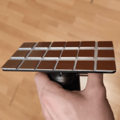
This vise is designed to be printed as a single piece, with very little post-processing required if your printer is dialed in. There is a small gap between the base plate and the springs and clamping surfaces that need to be separated with a painters knife or putty knife. Two “handles” have contours for your fingers to operate the clamping surfaces. It opens quickly for inserting your latest custom PCB.
PLA can be surprisingly flexible if the right geometry is used, and these springs are an excellent example of this. In the video below [Chuck Hellebuyck] does a test and review of the design, and it looks like it works well for hand soldering (though it probably won’t hold up well with a hot air station). Last month our own [Tom Nardi] recently reviewed a similar concept that used spiral springs designed into the printed part. While these both get the job done, [Tom’s] overall verdict is that a design like this rubber-band actuated PCB vise is a better long-term option.
Building the first commercial computers in the late 1950s and early 1960s was certainly a complex a task, but building the computer industry was even harder. Sure, engineers were already getting on board with designing in silicon and germanium instead of glass and tungsten, and all digital circuits are really just abstractions of analog designs most of them were already familiar with. But what about all the other people who would need to get up to speed on the workings of digital computers? What good is a tool if the only people who know how to use it art the ones who built it?
To make computers make money, companies needed legions of installers, operators, programmers, marketers, and salespeople, and all of them needed training. And so early computer companies put a lot of effort into building training devices to get people up to speed. These trainers helped teach everything from basic logic circuits and Boolean relationships to simple programming concepts, and each of them contributed in their own way to developing the computer industry that we know today.
Mike Gardi has a unique hobby: among other things, he builds faithful replicas of some of the nicer examples of these lost bits of computing history. His reproduction of Claude Shannon’s Minivac 601 trainer is a great example of the art, as is the DEC H-500 Computer Lab build he’s currently working on. Along the way, he’s explored some side alleys on the road to our computerized world, like Dr. Nim and the paperclip computer. All his builds are lovingly created from 3D-prints and really capture the essence of the toys and tools of the time.
Join us as we take a trip inside this niche realm of retrocomputing and find out why Mike finds it fascinating enough to devote the time it obviously takes to build such exacting replicas. We’ll talk about what projects he’s got going on right now, what he has planned for the future, and maybe even dive into some of his secrets for such great looking 3D prints.
Click that speech bubble to the right, and you’ll be taken directly to the Hack Chat group on Hackaday.io. You don’t have to wait until Wednesday; join whenever you want and you can see what the community is talking about.
For those getting started with 3D printers, thermoplastics such as ABS and PLA are the norm. For those looking to produce parts with some give, materials like Ninjaflex are most commonly chosen, using thermoplastic polyeurethane. Until recently, it hasn’t been possible to 3D print latex rubber. However, a team at Virginia Tech have managed the feat through the combination of advanced printer hardware and some serious chemistry.
Sample cubes printed with the new process. Note the clarity of the sample at the top right.
The work was primarily a collaboration between [Phil Scott] and [Viswanath Meenakshisundaram]. After initial experiments to formulate a custom liquid latex failed, [Scott] looked to modify a commercially available product to suit the project. Liquid latexes are difficult to work with, with even slight alterations to the formula leading the solution to become unstable. Through the use of a molecular scaffold, it became possible to modify the liquid latex to become photocurable, and thus 3D printable using UV exposure techniques.
The printer side of things took plenty of work, too. After creating a high-resolution UV printer, [Meenakshisundaram] had to contend with the liquid latex resin scattering light, causing parts to be misshapen. To solve this, a camera was added to the system, which visualises the exposure process and self-corrects the exposure patterns to account for the scattering.
It’s an incredibly advanced project that has produced latex rubber parts with advanced geometries and impressive mechanical properties. We suspect this technology could be developed quickly in the coming years to produce custom rubber parts with significant strength. In the meantime, replicating flexible parts is still possible with available filaments on the market.