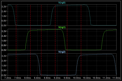
Like many of us [AnotherMaker] is a fan of the classic Forrest Mims electronics books, specifically, the Engineer’s Mini-Notebook series. They were great sources of inspiration, but at the time, he couldn’t afford to actually build most of the circuits described. Now as an adult, he decided to go through the 555 Timer IC Circuits Mini-Notebook, full of example circuits and explanations, all in Mims’ trademark handwritten style, and build all the circuits for real. And so, a series of YouTube videos are currently being released going over every circuit, how it works, and looking at waveforms on an oscilloscope!
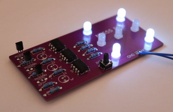
So, PCBs were designed, each containing four of the circuits from the book. With the Mims circuit diagram on one side of the screen and the PCB on the other, [AnotherMaker] goes into a good amount of detail explaining how each circuit works, referring to the schematic and oscilloscope as needed. Each part in the series focuses on the next circuits in order, and eventually the whole series will cover every single circuit in the book.
It’s a great series of videos for anyone learning electronics, especially those who would like to learn about one of the most produced integrated circuits of all time! It’s also an excellent way to bring a fresh perspective to this classic book, while simultaneously bringing the content to a wider audience via online video.