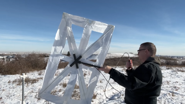
If you’d have asked us for odds on whether you could successfully turn a canned ham into an amateur radio antenna, we’d have declined the offer. Now, having seen [Ben Eadie (VE6SFX)]’s “hamtenna” project, we’d look at just about any “Will it antenna?” project with a lot less skepticism than before.
To be painfully and somewhat unnecessarily clear about [Ben]’s antenna, the meat-like product itself is not in the BOM for this build, although he did use it as sustenance. Rather, it was the emptied and cleaned metal can that was the chief component of the build, along with a few 3D printed standoffs and the usual feedline and connectors. This is a slot antenna, a design [Ben] recently experimented with by applying copper foil tape to his car’s sunroof. This time around, the slot was formed by separating the top and bottom of the can using the standoffs and electrically connecting them with a strip of copper tape.
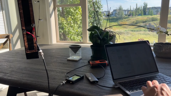
Connected to a stub of coax and a BNC connector, a quick scan with a NanoVNA showed a fantastic 1.26:1 SWR in the center of the 70-cm ham band, and a nearly flat response all the way across the band. Results may vary depending on the size of canned ham you sacrifice for this project; [Ben]’s can measured just about 35 cm around, a happy half-wavelength coincidence. And it actually worked in field tests — he was able to hit a local repeater and got good signal reports. All that and a sandwich? Not too shabby.