Automating Plant Care

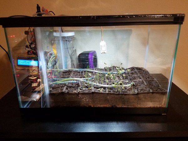
[Daniyal]’s goal is to build an automated garden that allows him to grow plants in any environment he chooses. He’s got a good start with this rig, which is controlled by a Pi Zero connected via serial to an Arduino Mega clone, which  in turn controls a bank of relays and sensors.

Monitoring the environment is a temperature and humidity sensor as well as a series of  six soil moisture sensor spikes. The relays control the water pump(s?) and lights, allowing [Daniyal] to maintain specific conditions depending on what he’s growing.

[Daniyal] has ambitious goals for the project. The Pi has a camera on it, and he hopes to not only maintain the greenhouse from the Internet, but also figure out how to monitor plant growth automatically, so that the Pi can measure plant growth and adjust the conditions without his input.

We’ve covered a lot of very cool horticulture projects here on HaD, including radio-connected soil sensors, using G-cal to create an internet of lawns, and the Garden of Eden watering kit.

Interactive Board Prompts Moves For Checkers And Chess

In terms of equipment, chess and checkers are simple games — just a handful of pieces and a checkered gameboard. The simplicity belies the underlying complexity of the games, though, and goes a long way toward explaining their popularity over the millennia.

Increasing the complexity with an interactive game board for chess and checkers might seem counterintuitive, then. But [Bogdan Berg]’s project aims to not only teach checkers and chess but to make games a little more exciting and engaging. Looking a little like a tabletop version of the interactive dance floors we’ve been seeing a lot of lately, the board is built from laser-cut acrylic with plywood dividers to isolate all 64 squares. Neopixels and Hall-effect sensors are mounted to custom PCBs that stretch the length of a row and are wired to an Arduino Mega with lots of IO. Game pieces are colorful fridge magnets. [Bogdan]’s current program supports checkers and keeps track of where the pieces have been moved relative to their starting position and prompts users with possible legal moves.

[Bogdan]’s board already looks like a lot of fun in the video below, and we like the quality of the build and the unobtrusive nature of the interactivity. When he gets around to implementing chess, though, he might want something fancier than fridge magnets for game pieces.

Continue reading “Interactive Board Prompts Moves For Checkers And Chess”

Well Engineered Radio Clock Aces Form And Function

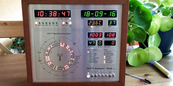
Clocks that read time via received radio signals have several advantages over their Internet-connected, NTP-synchronised brethren. The radio signal is ubiquitous and available over a fairly large footprint extending to thousands of kilometres from the transmitting antennae. This allows such clocks to work reliably in areas where there is no Internet service. And compared to GPS clocks, their front-end electronics and antenna requirements are much simpler. [Erik de Ruiter]’s DCF77 Analyzer/Clock is synchronised to the German DCF77 radio signal, which is derived from the atomic clocks at PTB headquarters. It features a ton of bells and whistles, while still being simple to build. It’s a slick piece of German hacker engineering that leaves us amazed.

Among the clock functions, it shows time, day of the week, date, CET/CEST modes, leap year indications and week numbers. The last is not part of the DCF77 protocol but is calculated via software. The DCF77 analyzer part has all of the useful information gleaned from the radio signals. There are displays for time period, pulse width, a bit counter, bit value indicator (0/1) and an error counter. There are two rings of 59 LEDs each that provide additional information about the DCF77 signal. A PIR sensor on the front panel helps put the clock in power save mode. Finally, there is a whole bunch of indicator LEDs and a bank of switches to control the various functions. On the rear panel, there are RJ45 sockets for the DCF77 receiver antenna board, temperature sensor and FTDI serial, a bunch of audio sound board controls, reset switches and a mode control switch.

His build starts with the design and layout of the enclosure. The front panel layout had to go through a couple of iterations before he was satisfied with the result. The final version was made from aluminium-coated sandwich-panel. He used an online service to photo-etch the markings, and then a milling machine to carve out the various windows and mounting holes. The rear panel is a tinted acrylic with laser engraving, which makes the neatly laid out innards visible for viewers to appreciate. The wooden frame is made from 40-year-old Mahogany, sourced from an old family heirloom desk. All of this hard work results in a really professional looking product.

The electronics are mostly off the shelf modules, except for the custom built LED driver boards. The heart of the device is an Arduino Mega because of the large number of outputs it provides. There are seven LED driver boards based around the Maxim 7221 (PDF) serial interface LED drivers – two to drive the inner and outer ring LEDs, and the others for the various seven-segment displays. The numerous annunciator LEDs are driven directly from the Arduino Mega. His build really comes together by incorporating a noise resilient DCF77 decoder library by [Udo Klein] which is running on a separate Arduino Uno. All of his design source files are posted on his GitHub repository and he hopes to publish an Instructable soon for those who would like to build one of their own.

In the first video below, he walks through the various functions of the clock, and in the second one, gives us a peek in to its inside. Watch, and be amazed.

Thanks for the tip, [Nick]

Continue reading “Well Engineered Radio Clock Aces Form And Function”

Stephen Hawking Forecasts The Weather

Stephen Hawking, although unable to speak himself, is immediately recognizable by his voice which is provided through a computer and a voice emulator. What may come as a surprise to some is that this voice emulator, the Emic2, has been used by many people, and is still around today and available for whatever text-to-speech projects you are working on. As a great example of this, [TegwynTwmffat] has built a weather forecasting station using an Emic2 voice module to provide audible weather alerts.

Besides the unique voice, the weather center is a high quality build on its own. An Arduino Mega 2560 equipped with a GPRS module is able to pull weather information once an hour. After the voice module was constructed (which seems like a project in itself) its relatively straightforward to pass the information from the Arduino over to the module and have it start announcing the weather. It can even be programmed to sing the weather to you!

All of the code that [TegwynTwmffat] used to build this is available on the project site if you’re curious about building your own Emic2 voice system. It’s also worth noting that GPRS is available to pretty much anyone and is a relatively simple system to start using to do things like pull weather information from, but you could also use it to roll out your own private cell phone network with the right equipment and licensing.

Huge Interactive Crossword

Give kids some responsible and challenging tasks, and you’d be surprised at the results. The “Anything Goes” exhibit at the National Museum in Warsaw was aimed as a museological and educational experiment. A group of 69 children aged 6–14 was divided into teams responsible for preparing the main temporary exhibition at the museum. Over six months, they worked on preparing the exhibition during weekly four-hour meetings. They prepared scripts, provided ideas for multimedia presentations, and curated almost 300 works for display. One of those was [Robert Mordzon]’s Giant Interactive Crossword.

The build is in two parts. The letter tiles, which have embedded RFID tags, obviously look like the easiest part of the build. The table, looking at the video (after the break), probably needed a lot more effort and labour. It is built in two halves to make construction easier. There are a 130 boxes that need to be filled in with the right letters to complete the crossword. Each box contains a bunch of electronics consisting of an Arduino Nano, a RFID Reader and a bunch of sixteen WS2812B LEDs, all assembled on a custom PCB. Do the math, and you’ll figure out that there’s 2080 LEDs, each capable of sipping 60 mA at full brightness. That’s a total current requirement of almost 125 amps at 5 V. Add in all the Arduino’s, and [Robert] needed a beefy 750 W of power, supplied via four switch mode power supplies.

Each Arduino Nano is a slave on the I²C bus. The I²C master is an Arduino Mega 2560, which in turn communicates with a computer over serial. When a box is empty, the LEDs are dim, when a wrong letter is placed, they turn Red, and when the right letter is placed, they turn Green. If a word gets completed, a special word animation is played. This information is also passed on to the computer, which then projects an animation related to the word on a giant wall screen. Upon the crossword getting completed, the table erupts in to a sound (via the computer) and light “disco” show and also reveals the main motto of this section of the exhibit – “Playing the Hero”.

Continue reading “Huge Interactive Crossword”

Scissors Make Great Automatic Cable Cutters

The team at [2PrintBeta] required a bunch of cables, heat shrink, and braid to be cut for their customers. They looked into an industrial cable cutter, but decided the price was a little too high, so they decided to make their own. They had a bunch of ideas for cutting: Using a razor blade?  Or a Dremel with a cutting wheel? What they came up with was a DIY cable cutter that uses a pair of scissors, a pair of stepper motors, a pair of 3D printed wheels and an Arduino.

The first thing the team had to do was to mount the scissors so they would cut reliably. One of the stepper motors was attached to a drive wheel that had a bolt mounted on it. This went through one of the scissors’ handles, the other handle was held in place on the machine using screws. The second stepper motor was used to rotate the wheels that drives the cable through to the correct length. [2PrintBeta] used a BAM&DICE shield and two DICE-STK stepper motor drivers on an Arduino Mega to control the cutter.

The [2PrintBeta] team are pretty good at doing things themselves, as we’ve seen previously with their DIY plastic bender. And again, with this automatic cable cutter, they’ve seen a need and resolved it using the things at their disposal and some DIY ingenuity.

Continue reading “Scissors Make Great Automatic Cable Cutters”

Hackaday Prize Entry: Mouse Controlled Microscope

You might imagine that all one should need to operate a microscope would be a good set of eyes. Unfortunately if you are an amputee that may not be the case. Veterinary lab work for example requires control of focus, as well as the ability to move the sample in both X and Y directions, and these are not tasks that can easily be performed simultaneously with only a single hand.

[ksk]’s solution to this problem is to use geared stepper motors and an Arduino Mega to allow the manual functions of the microscope to be controlled from a computer mouse or trackball. The motors are mounted on the microscope controls with a custom 3D-printed housing. A rotary selector on the control box containing the Arduino allows the user to select a slow or fast mode for fine or coarse adjustment.

It’s fair to say that this project is still a work in progress, we’re featuring it in our series of posts looking at Hackaday Prize entries. However judging by the progress reported so far it’s clear that this is a project with significant potential, and we can see the finished product could be of use to anyone operating the microscope.

We’ve featured one or two mouse controlled projects over the years, though not controlling microscopes. Here’s one mouse controlled robot arm, and we’ve covered another arm with a 3D mouse.