While split-flap alarm clocks once adorned heavy wood nightstands in strong numbers, today the displays are most commonly found in train stations and airports. Hey, at least they’re still around, right? Like many of us, [The Wrench] has always wanted to make one for themselves, but they actually got around to doing it.
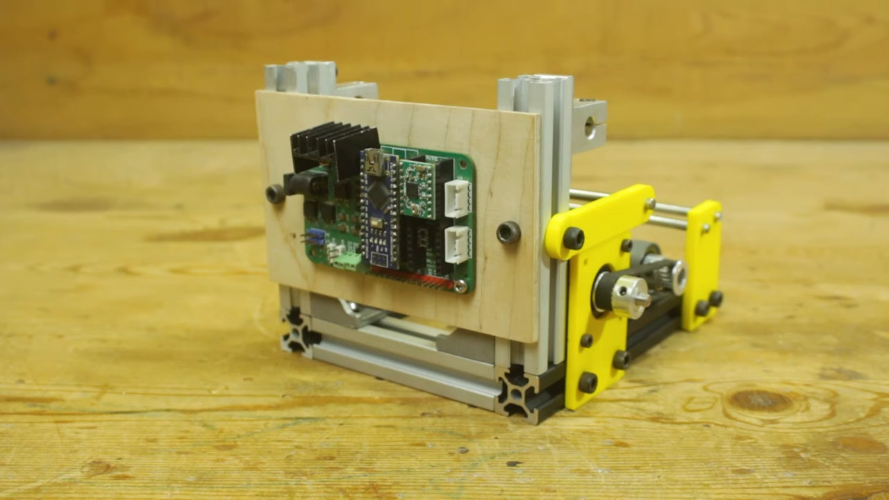
 This doesn’t seem like a beginner-friendly project, but [The Wrench] says they were a novice in 3D design and so used Tinkercad to design all the parts. After so many failures, they settled on a design for each unit that uses a spool to attach the flaps, which is turned by a stepper motor.
A small neodymium magnet embedded in the primary gear and a Hall effect sensor determine where the stepper motor is, and in turn, which number is displayed. Everything is handled by an Arduino Nano on a custom PCB.
Aside from the sleek, minimalist look, our favorite part is that [The Wrench] used even more magnets to connect each display segment to the base. You may have noticed that there are only three segments, because the hours are handled by a single display that has flaps for 10, 11, and 12. This makes things simpler and gives the clock an interesting look. Be sure to check out the build video after the break.
Want to build a more complicated clock? Try suspending sand digits in the air with persistence of vision.