While the vast majority of us are content to plod along with the squishy chiclet keyboards on our laptops, or the cheapest USB membrane keyboard we could find on Amazon, there’s a special breed out there who demand something more. To them, nothing beats a good old-fashioned mechanical keyboard, where each key-press sounds like a footfall of Zeus himself. They are truly the “Chad” of the input device world.
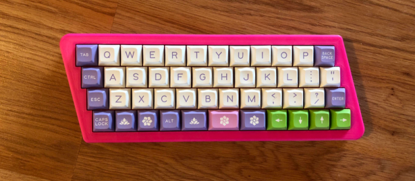
 But what if even the most high end of mechanical keyboards doesn’t quench your thirst for spring-loaded perfection? In that case, the only thing left to do is design and build your own. [Matthew Cordier] recently unveiled the custom mechanical keyboard he’s been working on, and to say it’s an elegant piece of engineering is something of an understatement. It may even look better inside than it does on the outside.
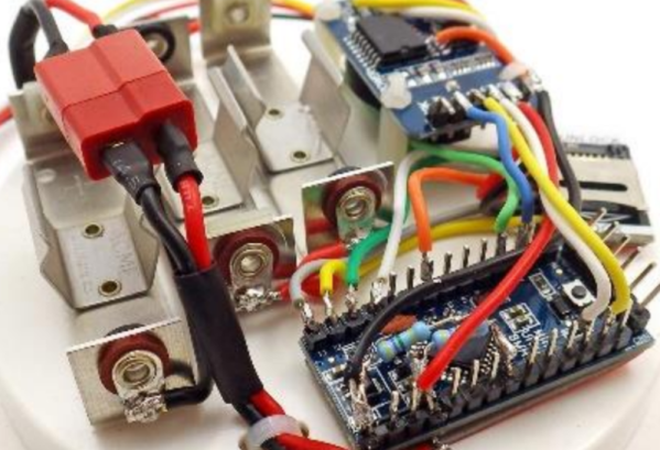
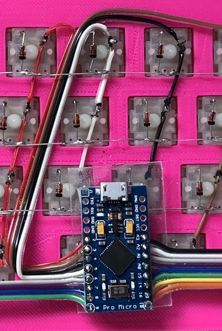
The keyboard, which he is calling z.48, is based around the Arduino Pro Micro running a firmware generated on kbfirmware.com, and features some absolutely fantastic hand-wiring. No PCBs here, just a rainbow assortment of wire and the patience of a Buddhist monk. The particularly attentive reader may notice that [Matthew] used his soldering iron to melt away the insulation on his wires where they meet up with the keys, giving the final wiring job a very clean look.
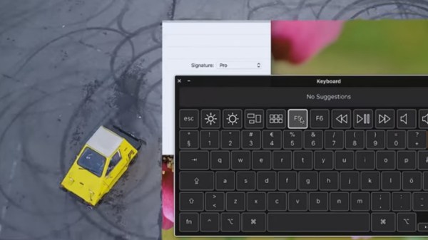
Speaking of the keys, they are Gateron switches with DSA Hana caps. If none of those words mean anything to you, don’t worry. We’re through the Looking Glass and into the world of the keyboard aficionado now.
Finally, the case itself is printed on a CR-10 with a 0.3 mm nozzle and 0.2 mm layers giving it a very fine finish. At 70% infill, we imagine it’s got a good deal of heft as well. [Matthew] mentions that a production case and a PCB are in the cards for the future as he hopes to do a small commercial run of these boards. In the meantime we can all bask in the glory of what passes for a prototype in his world.
We’ve seen some exceptionally impressive mechanical keyboards over the years, including the occasional oddity like the fully 3D printed one and even one that inexplicably moves around. But this build by [Matthew] has to be one of the most elegant we’ve ever come across.