
If you’re blessed with high water pressure at home, you probably love how it helps blast grime from your dishes and provides a pleasant washing experience. However, it can also cause a wonderful mess when that water splashes all over your countertops. [vgmllr] has whipped up a simple solution to this problem by installing an automatic splash guard.
The concept is simple enough—install a pair of flat guards that raise up when the sink is running, in order to stop water getting everywhere. To achieve this, [vgmllr] grabbed an Arduino, and hooked it up to a piezo element, which acts as a water sensor.
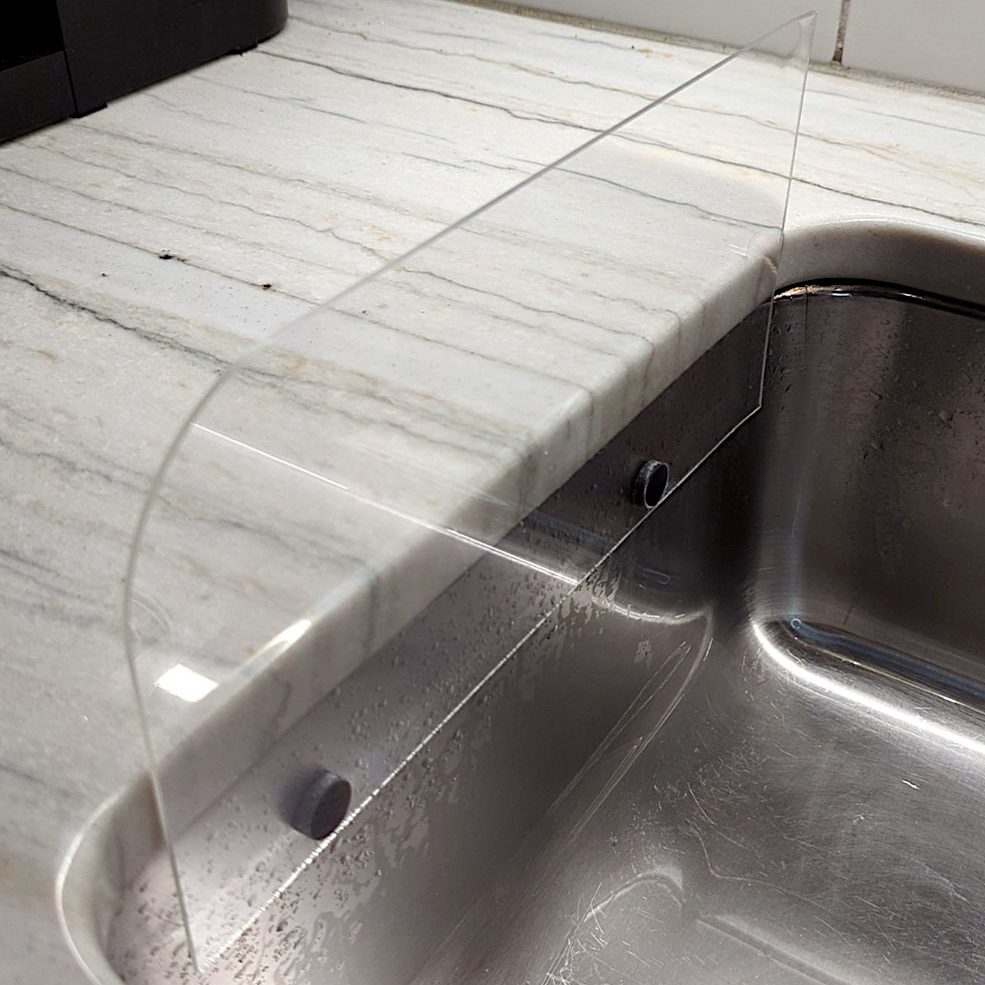
The piezo is attached to the bottom of the sink, and effectively acts as a microphone, hooked up to one of the Arduino’s analog-to-digital pins. When water flow is detected, the Arduino commands two servos to raise a pair of 3D printed arms that run up and down the outside of the sink. Each arm is fitted with magnets, which mate with another pair of magnets on the splash shields inside the sink. When the arms go up, the splash shields go up, and when the arms go down, the splash shields go down.
It’s an ingenious design, mostly because the installation is so clean and seamless. By using magnets to move the splash shields, [vgmllr] eliminated any need to drill through the sink, or deal with any pesky seals or potential water leaks. Plus, if the splash shields are getting in the way of something, they can easily be popped off without having to disassemble the entire mechanism.
It’s a tidy little build, both practical and well-engineered. It’s not as advanced as other kitchen automations we’ve seen before, but it’s elegant in its simple utility.


