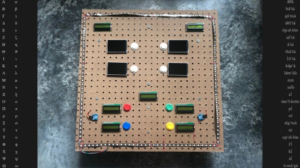
Learning a new language is hard work, but they say that the best way to learn something is to teach it. [Angeliki Beyko] is learning Greek, and what better way to teach than to build a vocabulary flash-card game from Arduinos, color screens, 1602 text screens, and arcade buttons? After the break, we have a video from the creator talking about how to play, the hardware she chose, and what to expect in the next version.
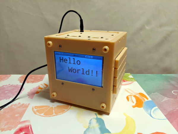
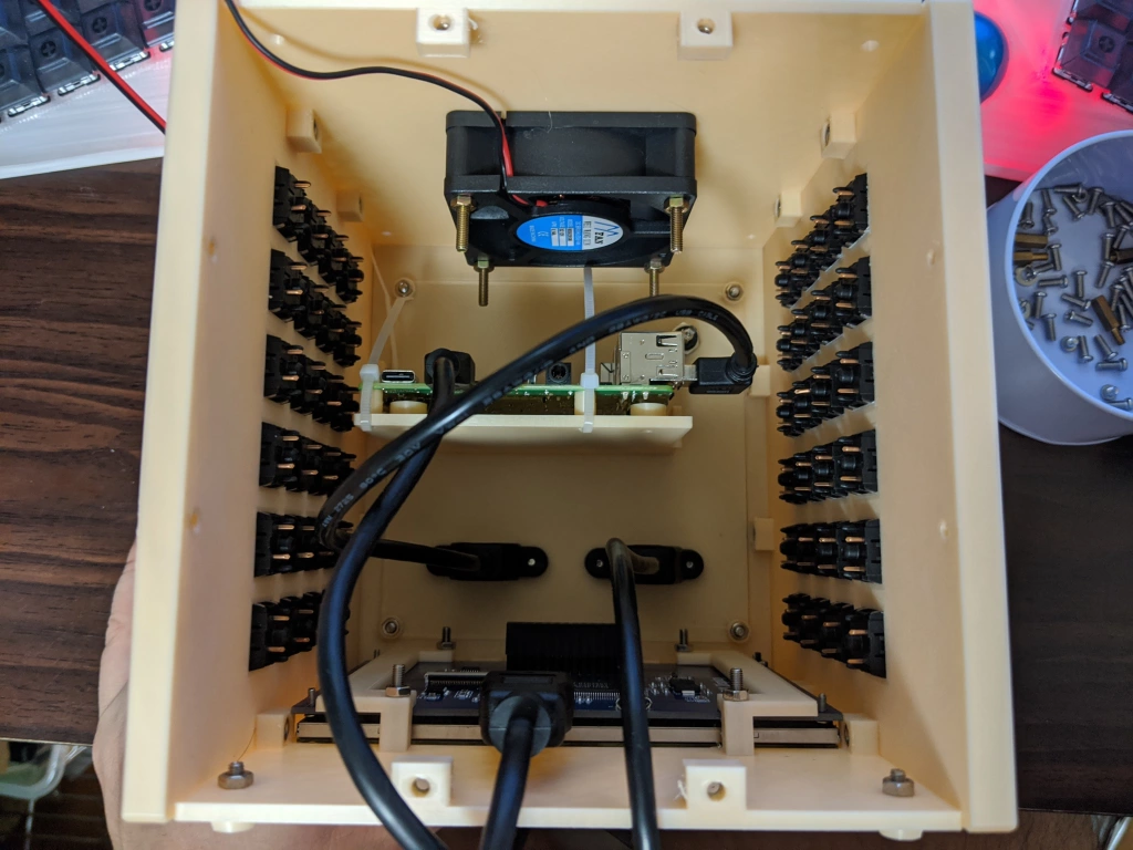
Pegboard holds most of the hardware except the color screens, which are finicky when it comes to their power source. The project is like someone raided our collective junk drawers and picked out the coolest bits to make a game. Around the perimeter are over one hundred NeoPixels to display the game progress and draw people like a midway game. Once invested, you select a category on the four colored arcade buttons by looking at the adjacent LCD screens’ titles. An onboard MP3 shield reads a pseudo-random Greek word and displays it on the top-right 1602 screen in English phonetics. After that, it is multiple choice with your options displaying in full-color on four TFT monitors. A correct choice awards you a point and moves to the next word, but any excuse to mash on arcade buttons is good enough for us.
[Angeliki] does something we see more often than before, she’s covering what she learned, struggled with, would do differently, and how she wants to improve. We think this is a vital sign that the hacker community is showcasing what we already knew; hackers love to share their knowledge and improve themselves.
Typing Greek with a modern keyboard will have you reaching for an alt-code table unless you make a shortcut keyboard, and if you learn Greek, maybe you can figure out what armor they wore to battle.