Passcode-Protecting The Means Of Caffeine

Several years ago, [Cameron] added an ATMega328-based PID temperature controller to his espresso machine. It has performed admirably to this day. But behind that cool bezel and LCD, all of the electronics are just sitting there, exposed. [Cameron] decided to give it a makeover. He has a better machine at home these days and wanted to take the old one to work. In order to keep untrained hands away from it in the office’s shared kitchen, [Cameron] installed a 4-digit keypad.

This makeover didn’t end with hiding wires and locking out noobs, though. [Cameron] added a float switch that will disable the pump when the water level gets too low. This is a nice touch. Otherwise, machines like this one will try to brew when the tank is dry, and then the pump has to be primed once the tank is refilled. [Cameron] also replaced the buttons’ back-lighting bulbs with bright LEDs. A small LCD mounted on the front of the machine shows the boiler temperature and shot-pulling duration.

If you’ve add PID temperature control to your espresso machine but have done nothing to improve the steam wand, why not add a pressure gauge?

Toy Television’s Dreams Come True

A couple of years ago, [Alec]’s boss brought him a souvenir from Mexico City—a small mid-century console television made of scrap wood and cardboard. It’s probably meant to be a picture frame, but [Alec] was determined to give it a better life.

As it turns out, the screen of [Alec]’s old Samsung I9000 was a perfect fit for the cabinet with room to spare. It was on its way to becoming a real (YouTube) TV once [Alec] could find a way to control it remotely. A giant new-old stock remote that’s almost bigger than the TV was just the thing. There’s enough room inside the remote for a non-LE Bluefruit module, which is what the I9000 will accept as input without complaint.

Trouble is, Bluefruit doesn’t support matrix keypads, so [Alec] used a bare ATMega328 running on the internal clock. Since the Bluefruit board provides voltage regulation, the remote was able to keep its native 9V power. [Alec] is happy with the results, though he plans to refine his button choices and maybe make a new overlay for the remote. Stay tuned for a tiny TV tour.

Continue reading “Toy Television’s Dreams Come True”

Hackaday Links: October 11, 2015

[Kratz] just turned into a rock hound and has a bunch of rocks from Montana that need tumbling. This requires a rock tumbler, and why build a rock tumbler when you can just rip apart an old inkjet printer? It’s one of those builds that document themselves, with the only other necessary parts being a Pizza Hut thermos from the 80s and a bunch of grit.

Boot a Raspberry Pi from a USB stick. You can’t actually do that. On every Raspberry Pi, there needs to be a boot partition on the SD card. However, there’s no limitation on where the OS resides,  and [Jonathan] has all the steps to replicate this build spelled out.

Some guys in Norway built a 3D printer controller based on the BeagleBone. The Replicape is now in its second hardware revision, and they’re doing some interesting things this time around. The stepper drivers are the ‘quiet’ Trinamic chips, and there’s support for inductive sensors, more fans, and servo control.

Looking for one of those ‘router chipsets on a single board’? Here you go. It’s the NixCoreX1, and it’s pretty much a small WiFi router on a single board.

[Mowry] designed a synthesizer. This synth has four-voice polyphony, 12 waveforms, ADSR envelopes, a rudimentary sequencer, and fits inside an Altoids tin. The software is based on The Synth, but [Mowry] did come up with a pretty cool project here.

Simple USB Power Meter

The USB interface is being increasingly used as a power supply and charging port for all kinds of devices, besides data transfer. A meter to measure the electrical parameters of devices connected to a USB socket or charger would be handy on any hacker workbench. The folks at [electro-labs] designed this simple USB power meter which does just that.

The device measures voltage and current and displays them, along with the calculated power, on the small 0.5″ OLED display. The circuit is built around an ATmega328. To keep the board size small, and reduce component count, the microcontroller is run off its internal 8MHz clock. A low-resistance shunt provides current sensing which is amplified by the LT6106 a high side current sense amplifier before being fed to the 10 bit analog port of the ATmega. A MCP1525 precision voltage reference provides 2.5V to the Analog reference pin of the microcontroller, resulting in a 2.44mV resolution. Voltage measurement is via a resistive divider that has a range of up to 6V. An Arduino sketch reads voltage and current data on the analog ports and displays measurements on the display. The measured data is averaged to filter out noise.

The OLED display has a SPI interface and requires the u8glib library. The project uses all SMD parts, but is fairly easy to assemble by hand and could be a nice starter project if you want to wet your feet on surface mount assembly techniques. It’s designed using SolaPCB EDA software, and the source files for schematic and board layout are available as a ZIP archive. Download the BoM and Arduino code and you have everything needed to build this nifty device.

Thanks to [Abdulgafur] for sending in this tip. And if you are looking for a more comprehensive solution, check the awesome Friedcircuits USB Tester which we reviewed earlier and is available in the Hackaday Store.

An Apple ][ Emulator On An Arduino Uno

April Fools’ Day may have passed, but we really had to check the calendar on this hack. [Damian Peckett] has implemented an Apple ][, its 6502 processor, and a cassette port, all on an Arduino Uno. If that wasn’t enough, he also uses a PS/2 keyboard for input and outputs analog VGA. [Damian] is doing all this with very few additional components. A couple of resistors, a capacitor and some very clever hacking were all [Damian] needed to convince an Arduino Uno that it was an Apple.

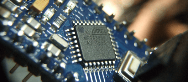
Making all this work boiled down to a case of resource management. The original Apple ][ had 4KB of RAM and 8KB of ROM. The ATmega328 has only 2KB of RAM, but 32KB of Flash. The only way to make this hack work would be to keep as much of the emulation and other routines in Flash, using as little RAM as possible.

The core of this hack starts with the MOS 6502, the processor used in the Apple. [Damian] wrote a simple assembler which translates the 6502 opcodes and address modes to instructions which can be executed by the Arduino’s ATmega328. To keep everything in ROM and make the emulator portable, [Damian] used two large switch statements. One for address modes, and a 352 line switch statement for the opcodes themselves.

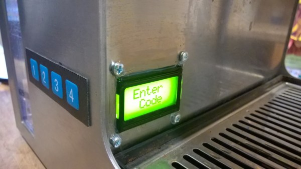
A CPU alone is not an Apple though. [Damian] still needed input, output, and the ROM which made the Apple so special. Input was through a PS/2 keyboard. The PS/2 synchronous serial clock is easy to interface with an Arduino. Output was through a custom VGA implementation, which is a hack all its own. [Damian] used the lowly ATmega16u2 to generate the video timing. The 16u2 is normally used as the Arduino Uno’s USB interface. The only external hardware needed is a single 120 ohm resistor.

The original Apples had cassette and speaker interfaces. So does this emulated Apple. [Woz’s] original cassette and speaker interface accurate loops to generate and measure frequencies. One of the trade-offs [Damian] accepted in his 6502 was cycle accuracy, so he couldn’t use the original routines. Not a problem though, as he was able to write simple functions to replace these routines and drop them in place of the Apple’s own ROM calls.

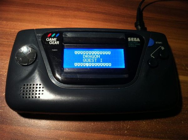
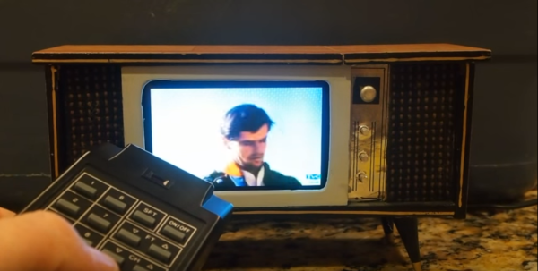
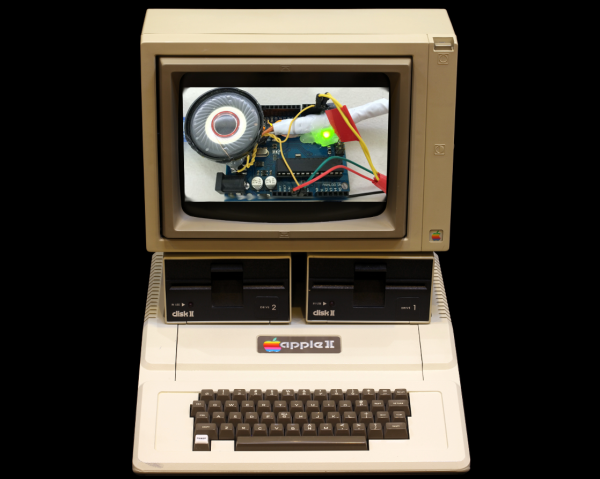
The Apple ][ ROM itself is handled as one giant character array. This includes the system monitor, Mini-Assembler, Sweet-16, and [Woz’s] own Integer Basic. [Damian] caps off this incredible project by booting his new computer, loading a  Mandelbrot set program from cassette -or in this case an audio file stored on his cell phone, and running it. The well-known fractal is displayed in all its glory on a modern LCD monitor, driven by a microcontroller, emulating a computer from nearly 40 years ago.

Continue reading “An Apple ][ Emulator On An Arduino Uno”

Automatic Garage Door Opener Works For Your Cat

Using an Arduino or Raspberry Pi to perform a task in the real world is certainly a project we’ve seen here before, and certainly most of these projects help to make up the nebulous “Internet of Things” that’s all the rage these days. Once in a while though, a project comes along that really catches our eye, as is the case with [Jamie’s] meticulously documented automatic garage door opener.

This garage door opener uses an ATMega328 to connect the internet to the garage door. A reed switch is installed which lets the device sense the position of the door, which is relayed back to the internet. [Jamie] wrote an Android app that can open and close the door and give the user the information on the door’s status. One really interesting feature is the ability to “crack” the garage door. This is done by triggering the garage door opener twice with a delay in between. From the video after the break we’d say this is how [Jamie’s] cat gets in and out.

We love seeing projects that are extremely well documented so that anyone who wants to make one can easily figure out how. Internet-connected garage door openers have been featured in other unique ways before too, but we’ve also seen ways to automatically open blinds or chicken coops!

Binary Clock

Binary Clock Would Make Doc Brown Proud

[Brett] was looking for a way to improve on an old binary clock project from 1996. His original clock used green LEDs to denote between a one or a zero. If the LED was lit up, that indicated a one. The problem was that the LEDs were too dim to be able to read them accurately from afar. He’s been wanting to improve on his project using seven segment displays, but until recently it has been cost prohibitive.

[Brett] wanted his new project to use 24 seven segment displays. Three rows of eight displays. To build something like this from basic components would require the ability to switch many different LEDs for each of the seven segment displays. [Brett] instead decided to make things easier by using seven segment display modules available from Tindie. These modules each contain eight displays and are controllable via a single serial line.

The clock’s brain is an ATmega328 running Arduino. The controller keeps accurate time using a DCF77 receiver module and a DCF77 Arduino library. The clock comes with three display modes. [Brett] didn’t want and physical buttons on his beautiful new clock, so he opted to use remote control instead. The Arduino is connected to a 433MHz receiver, which came paired with a small remote. Now [Brett] can change display modes using a remote control.

A secondary monochrome LCD display is used to display debugging information. It displays the time and date in a more easily readable format, as well as time sync information, signal quality, and other useful information. The whole thing is housed in a sleek black case, giving it a professional look.