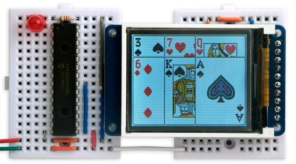
KittyOS: Writing A Toy OS For The ATmega168 From Scratch

Writing an operating system for a computing platform is one of those non-trivial tasks few people actually need to do, regardless of whether it’s for a small microcontroller or a larger general-purpose computer. Many of us spend a large amount of our time working on producing robust code for embedded systems, occasionally diving deeper into the abstraction when we’re stuck on a problem. Quite often this work is sitting on top of an RTOS, which we consider a solved problem. [Jonathan Diamond] had picked up a fair bit of knowledge of some of the low-level AVR black magic, as well as some details of how operating systems work internally, and so decided to have a crack a building a toy operating system called KittyOS, for the learning experience alone.

[Jonathan] hastens to add that this is not a practical OS, but a learning platform that needs a few more bells and whistles added to be useful. Aimed at the 8-bit AVR ATmega168 with its mere 16kB of flash and 1kB of SRAM, the diminutive chip can still perform more than well enough to host the rudimentary OS — up to four application tasks, and some basic system call support.

Already, KittyOS sports preemptive multitasking, with prioritization and support for applications written in C. Hardware support is a bit limited, with just serial I/O and a spot of GPIO, but that’s more than enough for a demonstrator. Applications can be loaded into any of the four available slots, with per-slot run state control, using the Python-based host interface. The post is a long one, with an absolute ton of the gory details we love around these parts, and we’re very glad [Jonathan] took the time to make a proper write-up as well as a demonstration video, which can be found after the break.

Continue reading “KittyOS: Writing A Toy OS For The ATmega168 From Scratch”

Blinking An Arduino LED, In Julia

The Julia programming language is a horrible fit for a no-frills microcontroller like the ATMega328p that lies within the classic Arduino, but that didn’t stop [Sukera] from trying, and succeeding.

All of the features that make Julia a cool programming language for your big computer make it an awful choice for the Arduino. It’s designed for interactivity, is dynamically typed, and leans heavily on its garbage collection; each of these features alone would tax the Mega to the breaking point. But in its favor, it is a compiled language that is based on LLVM, and LLVM has an AVR backend for C. Should just be a simple matter of stubbing out some of the overhead, recompiling LLVM to add an AVR target for Julia, and then fixing up all the other loose ends, right?

Well, it turns out it almost was. Leaning heavily on the flexibility of LLVM, [Sukera] manages to turn off all the language features that aren’t needed, and after some small hurdles like the usual problems with volatile and atomic variables, manages to blink an LED slowly. Huzzah. We love [Sukera’s] wry “Now THAT is what I call two days well spent!” after it’s all done, but seriously, this is the first time we’ve every seen even super-rudimentary Julia code running on an 8-bit microcontroller, so there are definitely some kudos due here.

By the time that Julia is wedged into the AVR, a lot of what makes it appealing on the big computers is missing on the micro, so we don’t really see people picking it over straight C, which has a much more developed ecosystem. But still, it’s great to see what it takes to get a language designed around a runtime and garbage collection up and running on our favorite mini micro.

Thanks [Joel] for the tip!

This DIY UPDI Programmer Is Nice And Cheap

[Daumemo] likes experimenting with DIY electronics, and like many people, eventually ran across an AVR microcontroller with a Unified Program and Debug Interface (UPDI). One option is of course to purchase an UPDI programmer, but an even better solution was to make a DIY USB version from nice, cheap parts.

Programming an Attiny404 over the UPDI interface.

UPDI is an interface for external programming and on-chip debugging of microcontrollers, and [Daumemo]’s solution is based on the jtag2updi project. It combines an Arduino Nano (in this case, a clone) with a single resistor, a single capacitor, and a six pin angled header (with a cleverly bent pin) to enable programming UPDI devices over a USB connection. [Daumemo] is happy to report that the device works just fine in both Microchip Studio with AVRDUDE, or PlatformIO.

Is an Arduino Nano a bit overpowered in this role? Maybe, but the price is certainly right. There’s no need for a custom PCB either, since everything can be soldered direct to the Nano board. A matching 3D printed enclosure is about all that’s needed to make a robust and reliable DIY USB UPDI programmer out of a handful of parts, and that sounds good to us.

On the other hand, if you do find yourself making custom PCBs, you may be interested in another of [Daumemo]’s DIY projects: a printable structure to turn a rotary tool into a PCB drill press.

Comfortable, wearable packaging for biometric device for monitoring physiological data and pushing the data to the cloud

A DIY Biometric Device With Some Security Considerations

Biohacking projects are not new to Hackaday and it’s certainly a genre that really piques our interest. Our latest biohacking device comes courtesy of [Manivannan] who brings his flavor of a wearable biosensor with some security elements built-in through AWS.

The hardware is composed of some impressive components we have seen. He has an AD8232 electrocardiogram front end, the MAX30102 integrated pulse oximeter IC for determining blood oxygen and heart rate, and the ever-popular LM35 for measuring body temperature. Either of these chips would be perfect for your next DIY biosensor project though you might try the MAX30205 body temperature sensor given its 0.1-degree Celsius accuracy. However, what really piqued our interest was the use of Microchip’s AVR-IoT WA Development Board. Now we’ve talked about this board before and also mentioned you could probably do all the same things with an ESP-device, but perhaps now we get to see the board a bit more in action.

[Manivannan] walks the reader through the board’s setup and everything looks to be pretty straightforward. He ultimately rigged together a very primitive dashboard for viewing all his vitals in real-time, demonstrating how you could put together your own patient dashboard for remote monitoring of vitals or other sensor signals. He emphasizes that all this is powered through AWS, giving him some added security layers that are critical for protecting his data from unwanted viewers.

Though [Manivannan’s] security implementation doesn’t rise to the standard of medical devices, maybe it will serve as a case study in the growing open-source medical device movement.

Continue reading “A DIY Biometric Device With Some Security Considerations”

CRISS CP/M Provides Modern Hardware For A Classic OS

Today you might choose run Windows, Linux, MacOS or some other OS on your computer. Back in the 1980s however, you generally had little choice: a certain home computer came with a certain OS, and that was it. If yours was based on a Z80 processor, chances are it ran CP/M. While differences in hardware often made direct data exchange difficult, CP/M provided at least a basic level of software compatibility between various Z80-based computers. Although eventually supplanted by MS-DOS (which initially aimed to be compatible with CP/M), enthusiasts kept the classic OS running on old hardware throughout the 90s and even beyond.

[Igor] decided to make a 21st-century CP/M machine by designing the CRISS, a single-board computer based mainly on AVR microcontrollers. The CPU is a 20 MHz ATMEGA1284P, which imitates a 4 MHz Z80 through machine-code emulation. A pair of ATMEGA328s run the peripheral controller and a VGA output, so the CRISS can be used with modern monitors. True to its heritage however, the image is monochrome green-on-black, looking instantly familiar to users of Kaypros, Osbornes and other contemporary CP/M machines.

Software is loaded through an SD card that holds floppy images. The CRISS can directly run programs written for the Kaypro II and Robotron 1715 computers, although other platforms can be supported as well with a software upgrade. [Igor] shows it running programs ranging from the Turbo Pascal compiler to games like Xonix and Tetris.

Housed in a neat little case, the CRISS can communicate with standard PS/2 keyboards and serial printers. Even an Ethernet port is provided for those willing to experiment with network connectivity (a rare feature in the 1980s).

We love seeing modern retro builds like this; similar projects we’ve covered before include the compact ZZ80MB and the huge Z20X. Others have used different ways of running CP/M on modern hardware, such as booting it directly on a Raspberry Pi or emulating an Altair on an ESP32.

Custom Num Pad Does Double Duty As Macro Pad

Why buy a num pad or a macropad when you can build something new and beautiful, open source that bad boy, and be a hero to the community? We think that should be all the justification you ever need to build instead of buy, even if you think your thing is Just Another Keypad [JAnK] as [Clewsy] claims.

At first glance, JAnK appears to be a standard number pad with four macro keys across the top. But when you roll your own ‘board, all the keys are programmable. [Clewsy] took advantage of this by adding a second layer that’s accessible with (what else?) the Num Lock key. This switches JAnK over to 21-key macro pad mode.

[Clewsy] rolled their own PCB for this and used the venerable ATMega32u4 because of its HID and USB host capabilities. Every key is backlit, and these LEDs are driven by an MP3202 LED driver and PWM from the AVR. [Clewsy] was able to build a prototype by sawing the num pad off of a stainless steel key switch plate from another build, but eventually ordered JAnK its own custom, laser-cut, stainless steel plate. The lovely enclosure is made of spotted gum wood and an acrylic base.

Putting it all together proved to be a bit problematic. [Clewsy] soldered up the minimum viable components for testing and discovered that the ATMega’s VCC and GND pins were both shorted. This killed the AVR programmer, but not the chip itself, and [Clewsy] happened to have a spare. To add insult to injury, the Num Lock light didn’t work, but [Clewsy] was able to simply reverse the LED instead of ordering a new pile of boards. Check out the detailed write-up with code and tons of pictures over on [Clewsy]’s personal site.

One of the awesome things about this build is that [Clewsy] was able to re-use the code from macr0, which began life as a proof of concept for scanning key matrices, and retired to become a music and media controller.

Cerberus 2080 — Three-Headed Retro Computing Project

For seven months, [Bernardo Kastrup] at [TheByteAttic] has been realizing his childhood dream of building his own computer. It was this dream that steered him into the field of computer design at the age of 17. After thirty years in the industry, he finally has some time to design the computer he dreamt about as a kid. His requirements are ambitious: fully open design, gate-level details, thru-hole or PLCC for easy hacking, well-established processors with existing tool chains, low-cost development tools for CPLDs, no FPGA, standard ITX case compatible, and so on. He quite reasonably decides to use more modern electronics for video (VGA), keyboard (PS/2), and program storage (flash drive). Along the way, he chooses to put three processors on the board instead of one:

  • Zilog Z84C0010 (Z80)
  • WDC W65C0256 (6502)
  • AVR ATMEGA328 (RISC Controller)

When coming up with the concept and requirements, [Bernardo] had a fictitious alternate history in mind — one where there were follow-ups to the ZX80, PET/CBM, or TRS-80 from the late 1970s that were extensions to the original systems. But he also wanted a clean design, without cost-cutting gimmicks, in order to make it easier for learners to focus on computing itself — a didactic architecture, as he describes it. Turn the crank for seven long months, and we have the Cerberus 2080. [Bernardo] has put the design on GitHub, and made a video series out of the whole process, of which the introduction video is below the break. There’s even an online emulator developed by retro hacker  [Andy Toone].

We wrote about the 6502-based ERIC-1 project back in 2014 which shared the bus with an ATMEGA simulating ROM. The Minty Z80 project from 2019 also uses a similar technique. Thanks to [Frédéric] for sending us the tip.

Continue reading “Cerberus 2080 — Three-Headed Retro Computing Project”